RPR 551IS RPR 552IS/553IS
PSG/10445/1
RPR 550IS Series
TM1188 Issue 1Page 5 - 8
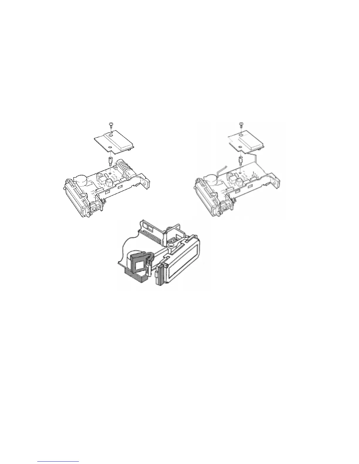
Figure 3: Exploded View
Re-assembly
14. The re-assembly is the reverse of the dismantling procedure except that the main board
must be inserted into the case at an angle, with the side containing the switches
inserted first. Swivel it around until it locates in the correct position. Ensure that the
contact fingers at the end of the decoder board are not disturbed and that the link wires
are correctly located.
FAULT-FINDING
15. Place a known good battery into the pager, switch on and refer to the fault-finding guide
(Figure 4). If the decoder circuit is suspected of being faulty proceed as follows:
a) Decase the pager (see Figure 2 and `Case Removal').
b) Separate the two PCBs and interconnect them with the 4-way lead supplied with the
P637F.