>0.5 %
C
A
>0.5 %
3
2
1
4
5
6
7
10
8
9
11
12
>0.5 %
17
15
18
19
B
B
D
16
B
13
14
E
>0.5 %
F
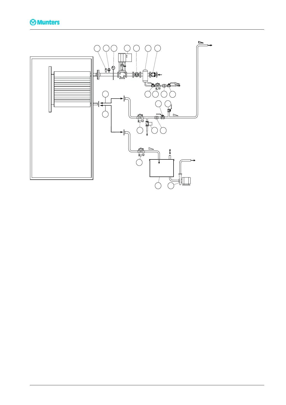
Figure 3.3 Installation of steam hea ter.
A. Steam supply D. Condensate drainage
B. Condensate return, dehumidifier E. Closed condensate return
C. Condensate return, drainag e F. Open condensate return
1. Thermal de-aerator 11. Ball valve
2. Vacuum valve 12. Steam trap (float)
3. Manometer 13. Condensate tank
4. Modulating steam valve 14. Pump
5. Mushroom valve 15. Steam trap (float)
6. Separator 16. Electromechanical valve
7. Steam filter 17. Non-retur n valve
8. Ball valve 18. Ball valve (shut-off valve)
9. Steam trap (float) 19. Ball valve (for connecting manometer)
10. Non-return valve
NOTE!
Componentsmarkedinboldmustalwaysbeinstalled.
22
Installation
190TEN–1089–G1412