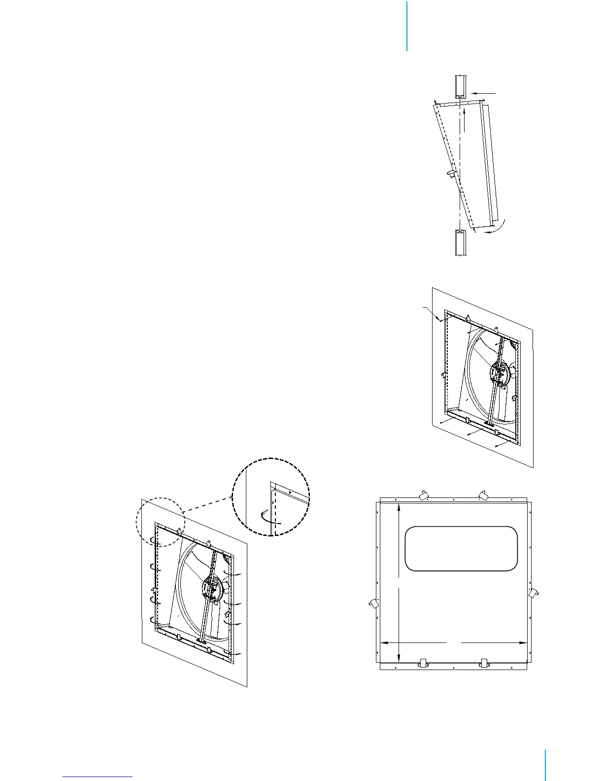
Step 2
Slide fan assembly into framed wall opening from outside
of the building. Insert top of fan into opening and hold fan
against top frame. Midpoint of top panel must be aligned
with frameing for bottom flange of fan to pass through
opening. See Figure 2. Secure top and bottom flanges to
wall using (6) Screws [A]. See Figure 3A.
Step 3
Left and right flanges must be bent outward over framing.
This can be done by hand or with a rubber mallet. Be
careful to bend along perforation and not to distort the
housing. See Figure 3B.
Step 4
Confirm that housing inside dimensions match those shown
in Figure 4A. Then secure left and right flanges to wall
using (10) Screws [A] (provided). See Figure 4B & 4C.
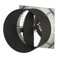
Step 5
Outlet of fan comes unguarded, install discharge cone
with guard on outlet of fan at this time. Refer to QM1049
for flat sided cone installation instructions.
Figure 2
Installation InstructionsChapter 2
Figure 3A
Figure 3B
60
1
⁄2”
Figure 4A
¼" x 1½ " Lag
screws [A]
Step 6
Make electrical connections to fan motor per instructions provided with fan or as shown on motor.
See Wiring Section on page 9.
NOTE:
This is NOT the Wall
Opening size.
56”