2.1 Fan Installation
Step 1
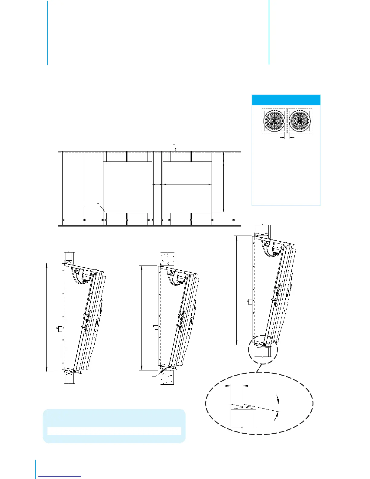
Construct framed opening to correct size according to the Wall Opening
listed in chart below. See Figure 1A, 1B,1C and 1D.
Installation Instructions
2.
Figure 1A
Ceiling
Framing
H
(see chart A)
12"
W
(see chart A)
See minimum spac-
ing notes in Chart A
Z
NOTE:
Chart A
A
2 x 4 framing
56½"W. x 62½"H.
Catalog No.
WF54
B
Concrete framing
56½"W. x 64"H.
Figure 1B
2 x 4 Framing
Figure 1C
Concrete Framing
Figure 1D
Greater than 4” Wall Thickness
B - Concrete Wall Opening
A - 2 x 4 Wall Opening
2 x 4
Framing cut
at 12° to
match fan
housing
3½"
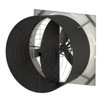
Fan with Discharge Cone:
a minimum clearance
of 12” on all sides is
recommended, but fans
may be installed with less
clearance if required. The
minimum center-to-center
distance is 60”.