MAINTENANCE
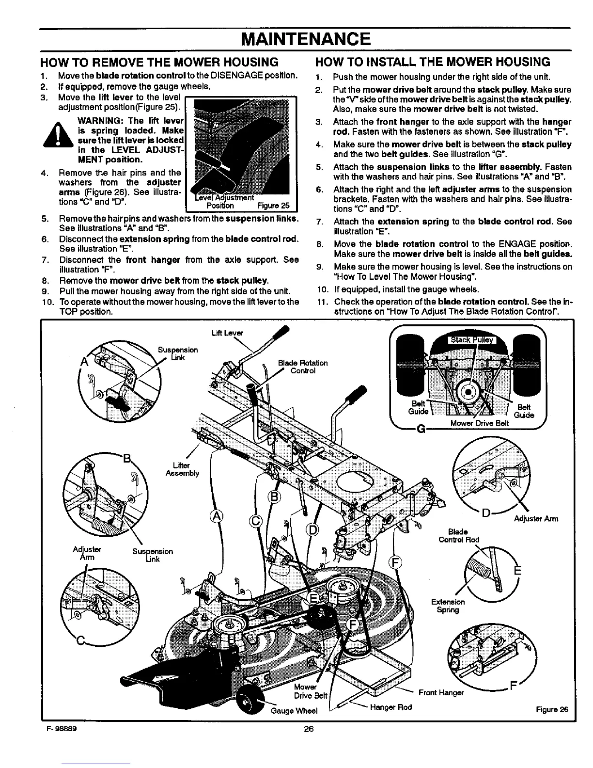
HOW TO REMOVE THE MOWER HOUSING
1. Move the blade rotation control to the DISENGAGE position.
2. If equipped, remove the gauge wheels.
3. Move the lift lever to the level
adjustment position(Figure 25).
WARNING: The lift lever
4_ia spring loaded. Makesurethe lift lever is locked
in the LEVEL ADJUST-
MENT position.
4. Remove the hair pins and the
washers from the adjuster
arms (Figure 26). See illustra-
tions =C" and _D'.
us_nent
Figure 25
5. Remove the hair pins and washers from the suspension links.
See illustrations =A" and =B".
6. Disconnect the extension spring from the blade control rod.
See illustration=E".
7. Disconnect the front hanger from the axle support. Sea
illustration=F".
8. Remove the mower drive belt from the stack pulley.
9. Pull the mower housing away from the rightside ofthe unit.
10. To operate without the mower housing, move the littlever to the
TOP position.
HOW TO INSTALL THE MOWER HOUSING
1. Push the mower housing under the right side of the unit.
2. Put the mower drive belt around the stack pulley. Make sure
the _ side ofth e mower drive belt is against the etaek pulley.
Also, make sure the mower drive belt isnot twisted.
3, Attach the front hanger to the axle support with the hanger
rod. Fasten with the fasteners as shown. See illustration=F".
4. Make sure the mower drive belt is between the stack pulley
and the two belt guides. See illustration"G'.
5. Attach the suspension links to the lifter assembly. Fasten
with the washers and hair pins. See illustrations"A" and =B'.
6. Attach the right and the left adjuster arms to the suspension
brackets. Fasten with the washers and hair pins. See illustra-
tions =C" and =D".
7. Attach the extension spring to the blade control rod. See
illustration=E'.
8. Move the blade rotation control to the ENGAGE position,
Make sure the mower drive belt is inside allthe belt guides.
9. Make sure the mower housing is level See the instructions on
=How To Level The Mower Housing'.
10. If equipped, install the gauge wheels.
11. Check the operation of the blade rotation control. See the In-
structions on "How To Adjust The Blade Rotation Control".
Lift Lever
Blade Rotation
Con_'ol
G, Mower Drive Belt
Lifter
Assembly
A_ster Suspension
Link
Adjuster Arm
Blade
Con_olRod
Extension_
Spnng
F- 98889
Mowof"
DriveBelt
GaugeWheel
26
Hanger Rod
Front Hanger
Figuro26