MAINTENANCE
HOW TO CHECK AND ADJUSTTHE DRIVEBRAKE
Completely push the brake pedal forward. Set the parking brake.
Move the automatic drive disconnect to the PUSH position. Push
the unit. If the rear wheels rotate, adjust or replace the brake pads.
Adjust the drive brake as follows.
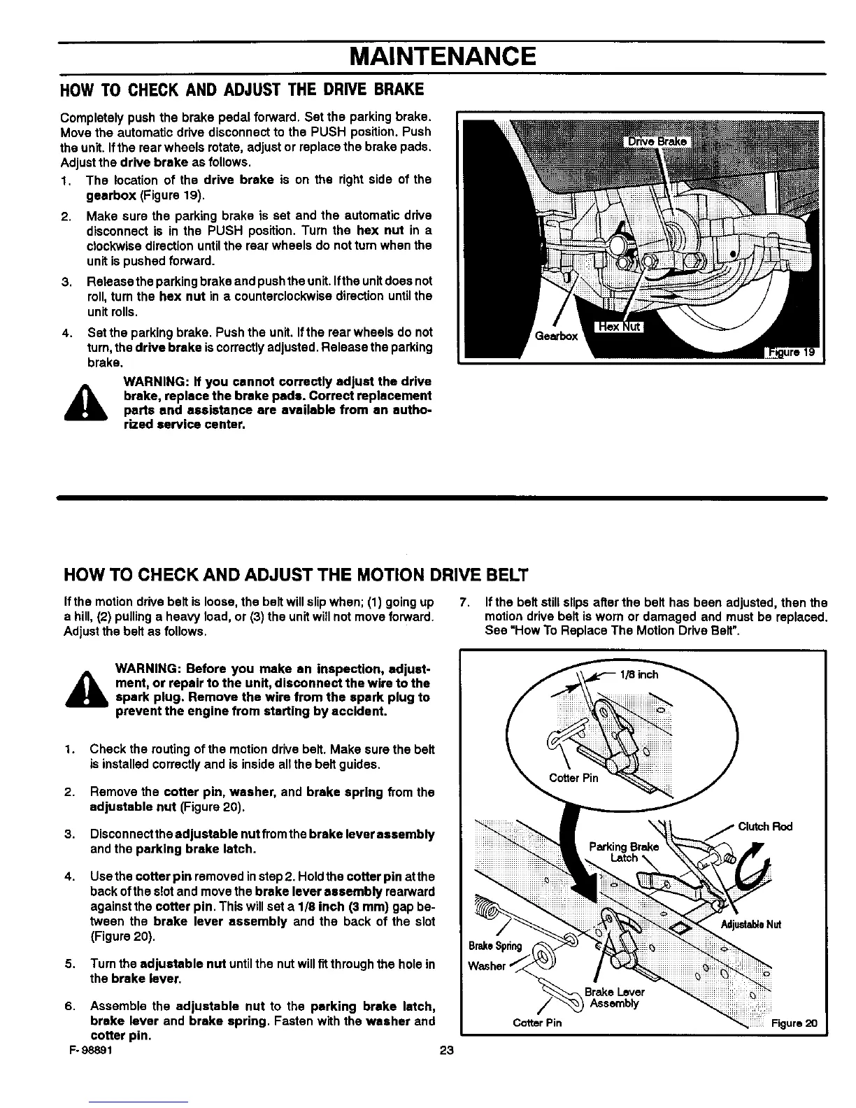
1. The location of the drive brake is on the right side of the
gearbox (Figure 19).
2,
3.
4.
Make sure the parking brake is set and the automatic drive
disconnect is in the PUSH position. Turn the hex nut in a
clockwise direction until the rear wheels do not tum when the
unit is pushed forward.
Release the parking brake and push the unit. Ifthe unit does not
roll,turn the hex nut in a counterclockwise direction untilthe
unit rolls.
Set the parking brake. Push the unit. Ifthe rear wheels do not
turn, the drive brake is correctly adjusted. Release the parking
brake.
A
WARNING: If you cannot correctly adjust the drive
brake, replace the brake pads. Correct replacement
parts and assistance are available from an autho-
rized service center.
HOW TO CHECK AND ADJUST THE MOTION DRIVE BELT
If the motion drive belt is loose, the belt will slipwhen; (1) going up 7. If the belt still slips after the belt has been adjusted, then the
a hill, (2) pulling a heavy load, or (3) the unitwill not move forward, motion drive belt is worn or damaged and must be replaced.
Adjust the belt as follows. See "How To Replace The Motion Drive Belt".
A
WARNING: Before you make an inspection, adjust-
ment, or repair to the unit, disconnect the wire to the
spark plug. Remove the wire from the spark plug to
prevent the engine from starting by accident.
2.
3.
4.
5.
Check the muting of the motion drive belt. Make sure the belt
is installed correctly and is inside all the belt guides.
Remove the cotter pin, washer, and brake spring from the
adjustable nut (Figure 20).
Disconnect the adjustable nut from the brake lever assembly
and the parking brake latch.
Use the cotter pin removed in step 2. Holdthe cotter pin at the
back of the slotand move the brake lever assembly rearward
against the cotter pin. This willset a 1/8 inch (3 mm) gap be-
tween the brake lever assembly and the back of the slot
(Figure 20).
Turn the adjustable nut untilthe nut willfit through the hole in
the brake lever.
6. Assemble the adjustable nut to the parking brake latch,
brake lever and brake spring. Fasten with the washer and
cotter pin.
F-98891 23
Cotter Pin
BrakeLever
Assembly
Clutch Rod
Figure 20