Chapter 5 Maintenance and Inspection
UD-series Screw Compressor 5.5 Reassembly
5-57
i) How to adjust if the end clearance is outside the specified value
(1) If the end clearance is greater than the specified value, if the clearance measured from
the discharge side of the bearing head at the end of the rotor is too large, the thrust
bearing must be tightened with a lock nut to narrow the end clearance.
Method 1: If the end clearance (A) (Figure. 5-24) is too large, sharpen the thrust bearing
alignment spacer to make it the same thickness as the difference between the
measurement result and the specified value.
Perform this work with a precise surface
grinder.
Measure the thickness of the washer around the entire circumference with a
micrometer to make sure it is parallel.
This adjustment method is available for all
models.
Method 2: Insert a shim material of appropriate thickness between the thrust bearing spacer
(partnumber 41) and the outer ring of the bearing.
The thickness of the shim material is the difference between the measured value and the specified
value.
Do not use brass or copper shim material as it will corrode if the refrigerant is ammonia.
(2) If the end clearance is smaller than the specified value, that is, if the rotor does not turn
after tightening the tightening bolts, the thrust adjustment washer (part number 42) is not
thick enough or the thrust bearing spacer is too thick.
For this adjustment, insert a shim
material of appropriate thickness between the thrust bearing alignment spacer (part
number 42) and the inner ring of the thrust bearing, or replace the thrust bearing
alignment spacer.
If the thrust bearing spacer (part number 41) is too thick, it must be ground.
After adjustment
by the above method, measure several times to check whether the end clearance is
appropriate.
j)Turn the M rotor shaft by hand and check if it rotates smoothly.
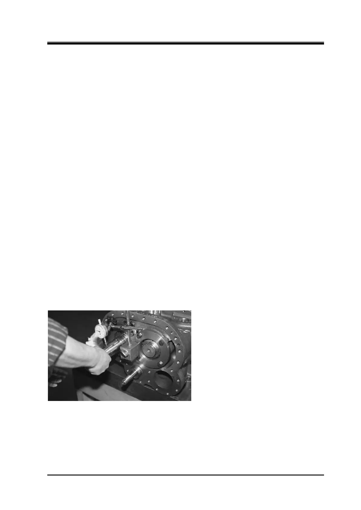
Inspection of axial runout
k) Use the dial gauge to check for radial runout at the M rotors indicated point.
The maximum
allowable runout width is 0.03 mm.
Swing may be caused by mismatch between the washer
and the spacer, and it is necessary to check again whether the V mark is set correctly.
Even if
the end clearance is specified value, disassemble and adjustment of the thrust bearing spacer
(part number 41) is important to maintain long life and high performance.
If there is dust