Chapter 5 Maintenance and Inspection
UD-series Screw Compressor 5.5 Reassembly
5-62
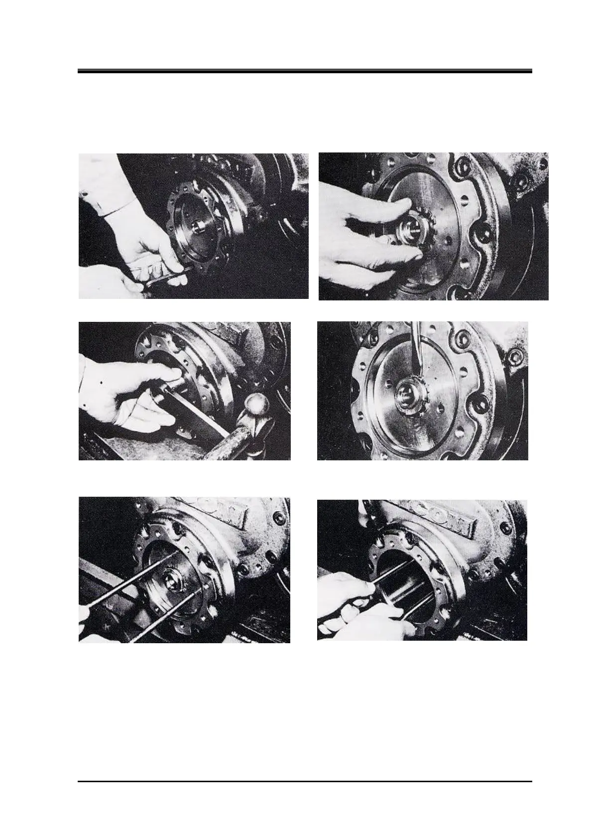
e) Screw two eye bolts into the unloader piston to check if the piston and slide valve are working
properly.
f)
Keep the unloader piston in the no-load position.
Setting the cylinder and balance piston cover
Setting Lock Washer and Lock Nut
Tigten the Lock Nut to the specified torque Bend the claws of the lock washer
Confirm operation with eyebolts
Full unloaded position (push to the end)
5.5.10 Unloader Cover
When disassembling the indicator cam shaft sealing part of the unloader cover, refer to the
development view in Figure 5-27,5-28 and assemble according to the following installation
procedure.
a) Assemble the ball bearing to the shaft of the indicator cam.
When pushing the bearing into the