2205Q2JE-HO-S6-N_2020.01.
Chapter 4 Compressor and Package Unit Operation
SCV-series Screw Compressor 4.1 Adjustment of Vi
4-3
e) Remove the domed cap nut [522] at the end of the Vi
adjusting rod, then loosen the hexagon nut [453] used
as a lock nut. On the compressors produced after
March in 2005, a conical spring washer is provided
between the hexagon nut and domed cap nut to prevent
detachment of the cap nut.
f) Turn the Vi adjusting rod clockwise until it stops.
The position where the rod stops corresponds to the H
port position the setting before shipment.
Do not turn the rod any further as applying undue force
will break the rotation stopping mechanism.
This position corresponds to that in Sequence (2) in
Figure 4-3.
Do not turn the Vi adjusting rod any further as applying undue force will break the
rotation stopping mechanism.
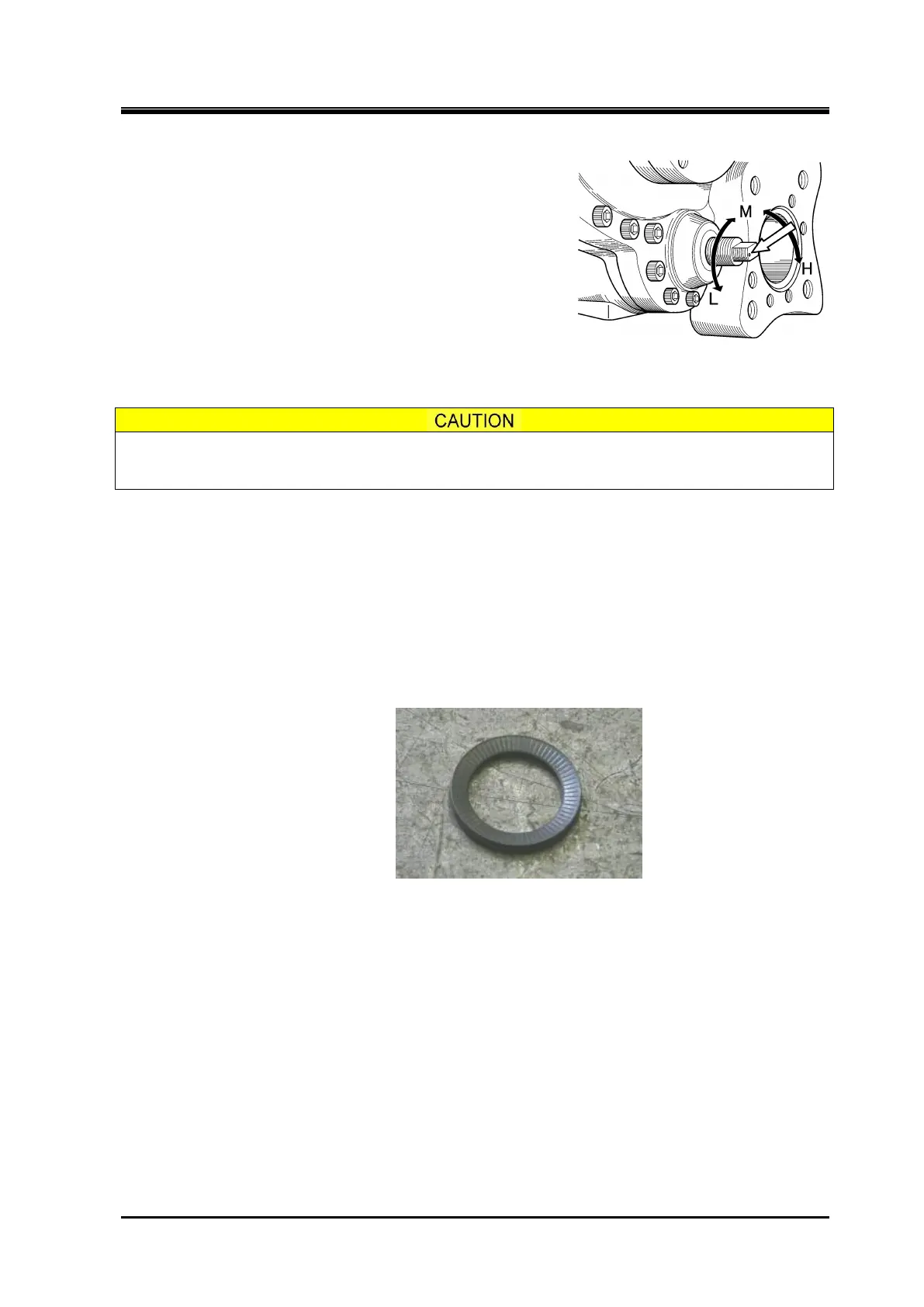
g) Check the inscribed mark (small black point indicated by the white arrow in Figure 4-1) on the Vi
adjusting rod, which should be used as a reference point when counting the number of turns of the
rod.
h) Turn the Vi adjusting rod counterclockwise by the number of turns determined in step (3). The Vi
setting will be changed from the H port setting to the M port setting as shown in Sequence (3) in
Figure 4-3.
i) While holding the Vi adjusting rod against rotation, lock the rod by tightening the lock nut.
j) Install the domed cap nut to the end of the Vi adjusting rod and tighten it. Do not fail to install the
conical spring washer between the hexagon nut and domed cap nut to prevent detachment of the
cap nut due to vibration, or like.
Figure 4-2 Conical Spring Washer
k) By releasing lockout/tagout of the electric power breaker temporarily, and then turn on the control
power and the oil pump power.
m)
Supply oil pressure to increase the capacity control by individual oil pump operation until the slide
valve stops at the full loaded position.
n) If the pointer of the unloader indicator aligns with the 100 % graduation for the port in question on
the dial, the Vi is correctly adjusted to that port. This is the Sequence (4) in Figure 4-3.
The M and H graduation marks are rather large in width.
This is because there is a slight difference in indication of the M and H positions among the 13
compressor models, i.e. 160S/M/L, 200S/M/L, 250S/M/L/LL, and 320S/M/L, due to difference in
rotor length. The setting may be considered correct if the needle pointer indicates any point in the
width of the graduation mark.
Figure 4-1 Vi Adjusting Rod