2205Q2JE-HO-S6-N_2020.01.
Chapter 5 Maintenance and Inspection
SCV-series Screw Compressor 5.4 Disassembly and Inspection
5-16
■ For Further Disassembly (In the case of Removing as Unloader Indicator Assembly)
As the indicator is an assembly to be removed as a whole, no further disassembly should be made
unless the purpose of the disassembly is to disassemble this part.
a) As a result of the previous disassembly process, the micro switch base plate [121], which is
mounting the potentiometer [129], micro switches [125], and micro switch cam [127], can be
removed.
b) Unscrew and remove three hexagon socket head cap screws [122].
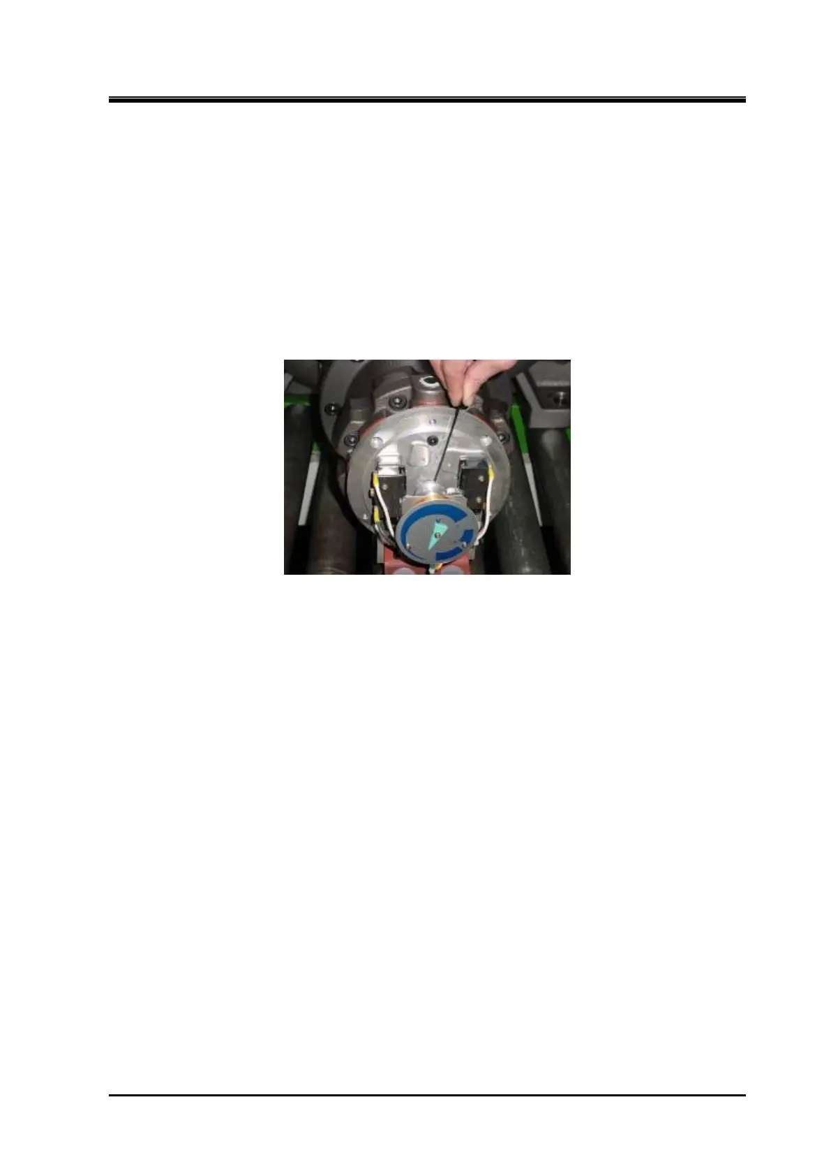
c) Loosen the set screw [128] of the micro switch cam.
d) After that, the assembly can be removed by pulling it in the axial direction.
Loosen the Set Screw of the Micro Switch Cam
5.4.1.2 Inspection
The inspection procedure is described in the "Reassembly" section of this chapter, as it is often the
case that the unloader indicator block is removed as an assembly and later inspected and adjusted
after the overhauled compressor is reassembled and installed on the mounting base. Refer to Section
5.5.12 "Unloader Indicator" for details.