2205Q2JE-HO-S6-N_2020.01.
Chapter 5 Maintenance and Inspection
SCV-series Screw Compressor 5.5 Reassembly
5-42
5.5.7.1 End Clearance Measurement
At this point (i.e., after the thrust bearing block has been fully assembled), measure the end clearance
of the rotor on the discharge side.
In particular, this measurement must be made when the thrust bearing has been replaced. Even if the
same bearing is used, the measurement should be made for verification.
If the measured clearance does not satisfy the range specified in Table 5-9, proper adjustment must be
made.
Table 5-9 Specified Limits of End Clearance (unit: mm)
Model
for Single Stage (High Stage) Use
for Booster (Low stage) Use
L LL
L LL
160V** 0.04~0.06 - 0.20~0.22 0.22~0.24 0.24~0.26 -
200V** 0.05~0.07 - 0.26~0.30 0.28~0.32 0.31~0.35 -
250V** 0.08~0.11 0.40~0.44 0.45~0.49 0.50~0.54 0.55~0.59
320V*D 0.17~0.21 0.20~0.24 0.23~0.27 - 0.70~0.76 0.73~0.79 0.77~0.83 -
a) For pressing the rotor shaft on to the discharge side, hit the rotor shaft strongly from the suction side
while putting a jig (Teflon block or like).
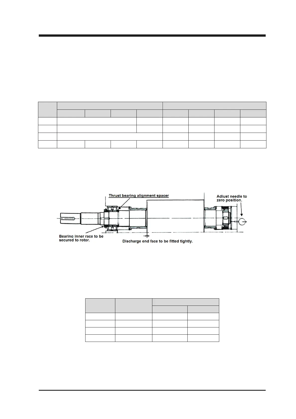
b) Prepare the thrust bearing gland to be readily mounted. Mount a dial gauge on the axial end of the
rotor, and set the indication needle to zero point while the rotor is fully pressed onto the discharge
end face.
Figure 5-16 End Clearance Measurement Preparation
c) Without inserting the conical spring washer [46], tighten the four fastening bolts [45] of the bearing
gland sequentially and evenly up to the specified tightening torque. Tightening each bolt at once at
the specified torque must be avoided because it will result in uneven tightening. So Tighten with the
procedure shown in 7.3.4.
Table 5-10 Tightening Torques of Thrust Bearing Gland
Model Bolt Size
M10x30 40 400
M12x35 50 500
M20x55 120 1200
d) Then, read the dial gauge indication. This value shows the actual end clearance. If the end
clearance is outside the specified value, perform the adjustment work described in the next section.
If the end clearance is within the specified value, turn the M rotor shaft by hand and confirm the
smooth turning without uneven tightening. And then perform the measurement of the run-out of the
rotor shaft described in next section (3).