2203M4JE-MY-iS2-N_2017.04.
Chapter 5 Maintenance
Screw Compressor i-series 5.5 Reassembly
5-24
5.5.6 Adjustment of Thrust Bearing and End Clearance
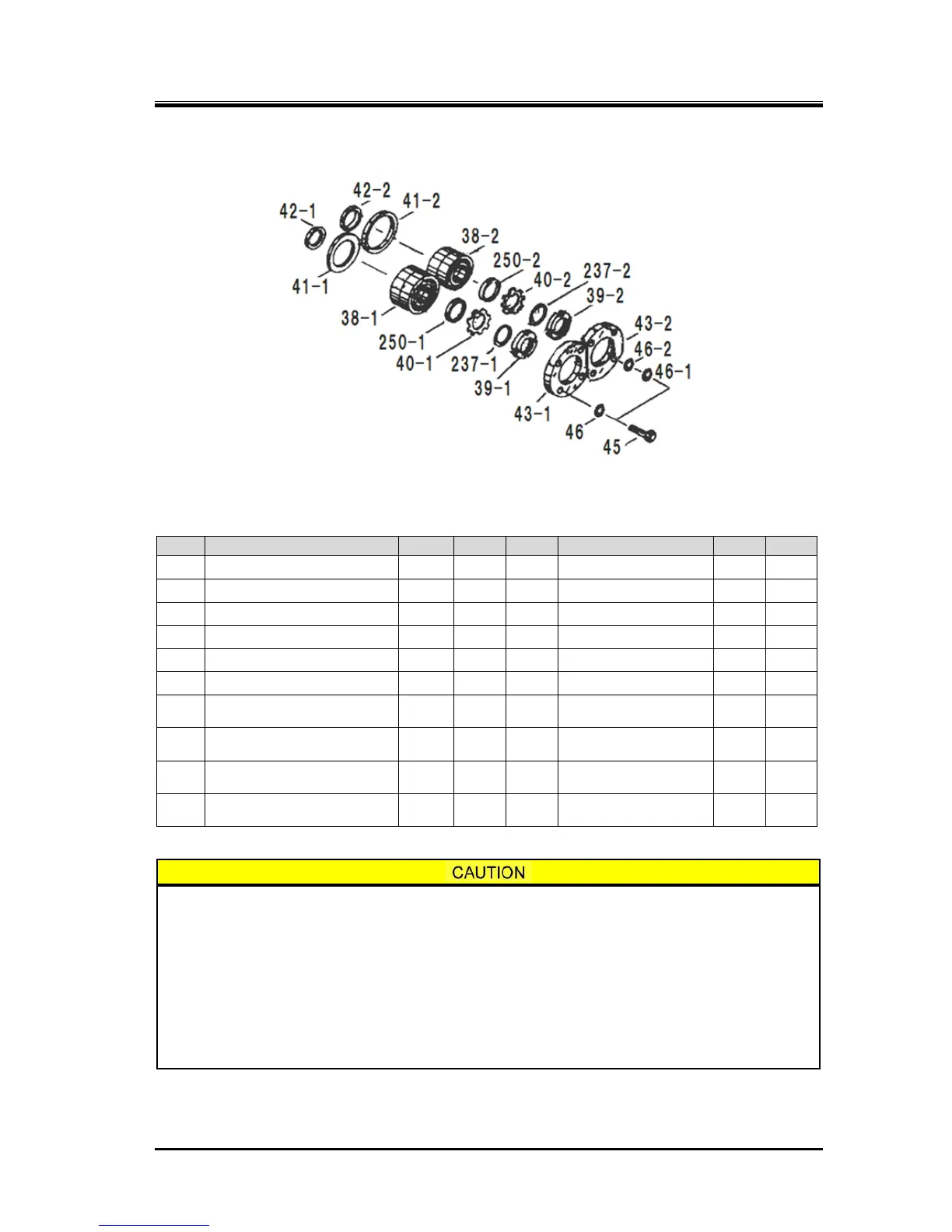
Figure 5-4
Thrust Bearings Block
Table 5-12
Thrust Bearing Components
When assembling the disassembled thrust bearing without replacing any parts,
check the M and F stamp marks on the thrust bearing outer race spacer and thrust
bearing alignment spacer, and reassemble them in the same way as before
disassembly. This is essential to control the end clearance of the rotor discharge
side.
Even when assembling the same bearing, dimensions may become incorrect if flakes
of paint or dirt are caught between outer race spacers and alignment spacers.
Regarding the direction of thrust bearing assembly, there may or may not be a
V-shaped mark for assembly on the outer side of the bearing. Follow the instructions
below for each case of assembling.
38-1 Thrust Bearing M 1 set 1 set 43-1 Thrust Bearing Gland M 1 1
38-2 Thrust Bearing F 1 set 1 set 43-2 Thrust Bearing Gland F 1 1
39-1 Lock Nut 1 1 45 Hexagon Head Bolt 8 8
39-2 Lock Nut 1 1 46 Spring Washer 8 -