2203M4JE-MY-iS2-N_2017.04.
Chapter 5 Maintenance
Screw Compressor i-series 5.5 Reassembly
5-25
a) The procedure for assembling this block is described in Figure 5-4.
The important points are explained below.
If there is a V-shaped mark for assembly on the outer side of the thrust bearing, assemble with the
pointed end of the mark on the inner side of the machine, as there is a slight directional difference
that affects end clearance adjustment.
If there is no V-shaped mark, assembly direction does not affect end clearance adjustment.
However, to clarify the difference between the inner side and outer side of the machine, assemble
the thrust bearing with the bearing number engravings on the outer side and then put down a
V-shaped mark on the machine's inner side by using blue sharpening stone.
b) After assembling the thrust bearing, install thrust washers [41-1] [41-2], lock washers [40-1][40-2]
and torsional slip washers [237-1] [237-2].
c) Attach dedicated shaft rotation stoppers 1 and 2. Tighten lock nuts [39-1] [39-2] to the specified
torque shown in Table 5-13 or to the specified tightening angle shown in Table 5-14 (refer to Section
7.1 "Tightening Angles for Lock Nuts" in this manual for details), to fix the inner race of the thrust
bearing to the rotor shaft. Be sure to use a new lock washer.
Tightening the lock nut while keeping the setting position between the lock nut wrench hooks
and the lock nut grooves may cause to make the rotor run-
out to enlarge due to uneven
tightening forces.
Change the setting pos
ition between the lock nut wrench hooks and lock nut grooves about four
times when fastening the lock nut.
d) Turn the M rotor shaft by hand, to make sure that rotation of rotors is smooth.
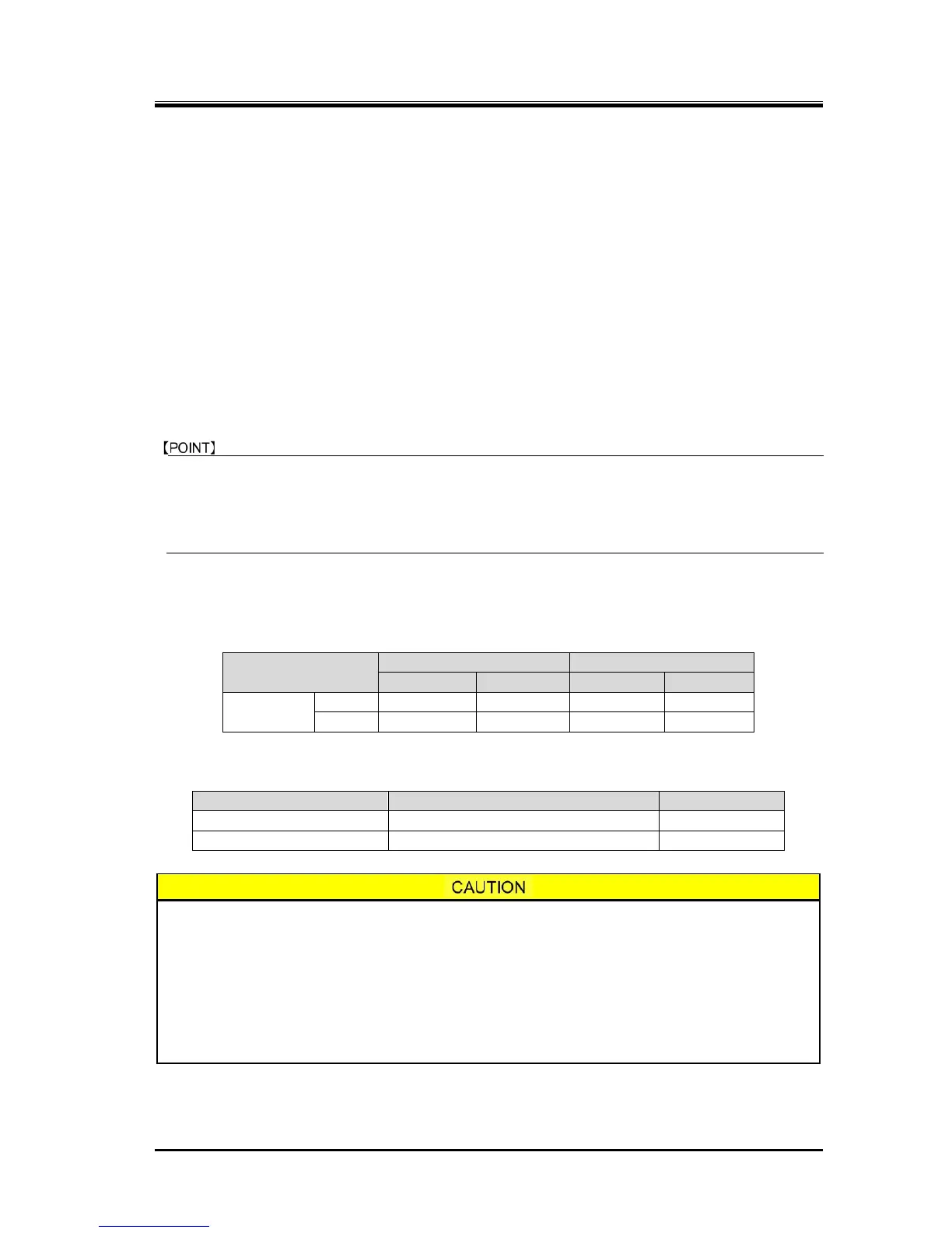
Table 5-13 Tightening Torques for Lock Nuts
Table 5-14 Tightening Angles for Lock Nuts
For both M and F rotors (i125* / i160*)
Second turn of tightening
For both M and F rotors (i125* / i160*)
Since the inner race of the thrust bearing is loose fit and is secured by the tightening
force of the nut alone, the tightening work is very important.
If the thrust bearing has been replaced, the difference between the bearing inner race
and outer race surfaces will be different even when the parts are manufactured within
standard values. Therefore, fully tightening the nut from the initial use may lead to a
noticeable reduction in the life of bearing, due to a lack of end clearance between the
rotor and the bearing head discharge end face, and also due to indentations on the
contact surface formed by ball pressure. To avoid this, check for end clearance while
tightening.
 Loading...


