Chapter 7 Related Documents
UD-series Screw Compressor 7.4 Lock Nuts
7-36
7.4 Lock Nuts
Table 7-14 Lock Nut Used and Each Tightening Torque
P/N
Location
Nominal Designation of Lock Nut(Qty)
Tightening Torque N・m
39 Thrust Bearing
Standard/Maximum
AN09(2)
206/258
AN12 (2)
408/510
AN13 (2)
522/653
AN17 (2)
1186/1483
AN21 (2)
2259/2824
AN28(2)
5347/6683
69 Unloader Piston
AN05(2)
AN05 (1)
AN07 (1)
AN08 (1)
AN10 (1)
AN10(2)
When tightening a lock nut, if it is difficult to use a torque wrench, manage the tightening torque of the
lock nut controlling the tightening angle range as explained below.
Distortion correction of slip washers and lock washers
a) Tighten the lock nut by hand.
b) Use a lock nut wrench and tighten until the rotor turns.
c) Use a lock nut wrench and a hammer, hit twice lightly.
d) Use a lock nut wrench and a hammer, loosen the lock nut.
Tightening Angle Range of Lock Nuts for Rotors
a) After tightening the lock nut by hand, further tighten the lock nut by using a lock nut wrench until the
rotor starts to turn. Take care not to over-tighten.
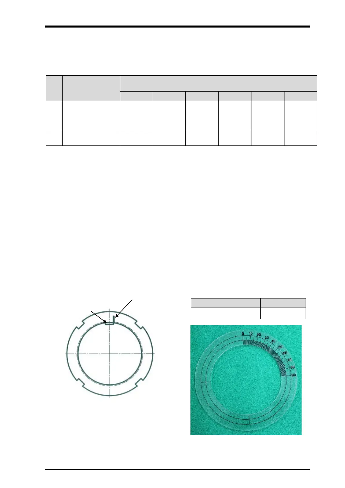
b) Put a mark on the lock nut at the right side edge of the rotor groove where the stopper tongue of the
lock washer fits in, as shown in Figure 7-8.
c) From this marking position, tighten the lock nut in such a way that rotation can be stopped within the
tightening angle range shown in Table 7-15.
When measuring the angle, use an angle gauge which is set to the diameter of rotor shaft.
Table 7-15 Tightening Angles Specified
for Lock Nuts of Rotor
125** - 400** 15° to 30°
Figure 7-8 Position where mark is put
Angle gauge (example)
where stopper tongue of
 Loading...


