24 V
~
L
N
L
1
2
TA
N
TA
L
1
2
TA
N
TA
L
1
2
TA
N
L
TA
N
L
N
L
N
L
N
1
2
PumpBoiler
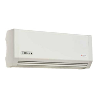
Myson 24V Room Thermostat
Code 50507
Max limit
Normal
setting
Min limit
6C
12C
24C
18C
30C
Daytime temp
L
N
230V timed supply
from programmer
Mains input
L
N
L
N
Potential free
relays
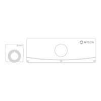
Installation and operating instructions
UFH Wiring Centre 24V (no. 63050599401)
Fig. 1 Room Thermostat 24V, Wiring centre 24V
1. OVERVIEW / FUNCTION
This manual describes the function and installation of
the wired Under Floor Heating (UFH) control system.
The wired UFH system consists of two key components: The
Myson 24V wiring centre and the Myson 24V room thermostat.
The system is approved for use in the EU and EFTA countries.
The wiring centre is prepared with a built-in 50VA transfor-
mer and terminals for thermostats and actuators. Each
terminal block is clearly marked with symbols that facilitate
easy and problem free installation. Each wiring centre can
control up to ten heating zones and twelve actuators
Wiring Centre (no.
63050599401)
Phase 24V → Terminal L
Neutral 24V
→ Terminal N
Switched phase
→ Terminal
2. MOUNTING / INSTALLATION
Position the wiring centre right above the underfl oor heating
manifold, either on the wall or inside the manifold cabinet.
The wiring centre must be mounted horizontally and in a
way that facilitates access, and easy removal of the cover.
Caution !
The wiring centre must not be exposed
to splashes of water (IP20).
The power supply must be disconnected
before proceeding with the installation.
Loosen the three screws and lift the cover.
Connect the wires from the thermostats to the
corresponding terminals in the wiring centre. See fi g. 2a.
Remember to register the location of the thermostat.
Connect the cables from the actuators to the relevant
terminals. If a thermostat controls more than one
actuator, make the connection as shown in fi g. 2b.
Secure cables in the strain reliefs. See fi g. 3a + 3b.
Replace the cover on the hinges above and close the cover.
Tighten the three screws and connect the plug to 230V.
Pump relays: The wiring centre is provided with 2 potential-
free relays, for controlling the UFH circulation pump and
boiler or zone valve. The relays are activated, when
one or more thermostats require heat. See fi g. 2a.
10
20
30
d
Fig. 2 a