B1
9
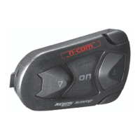
Fig. 5
Fix the cable inside the helmet and
make sure the right fixing clip snaps
into its housing (Fig. 5)
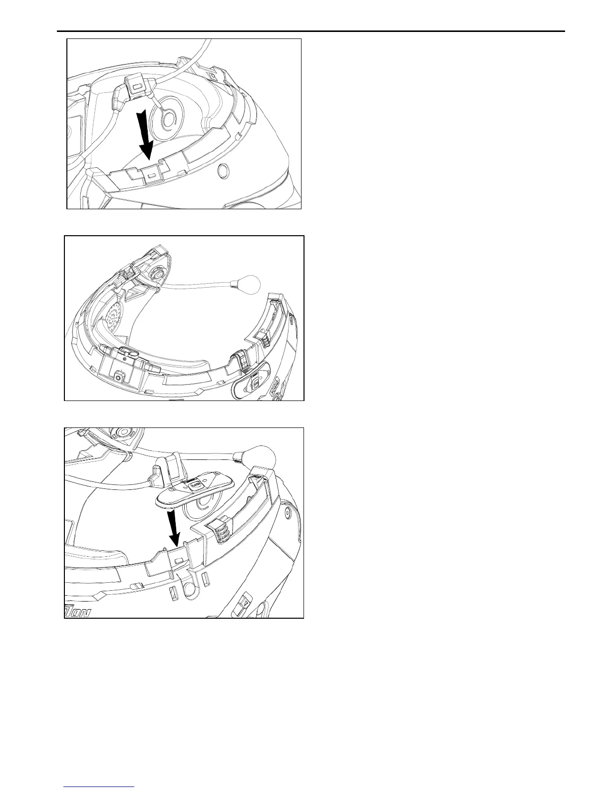
Fig. 6
Position the microphone in the
housing on the left of the helmet,
inserting the metal boom in the
groove found in the chin guard
coupling frame (Fig. 6).
Caution: make sure that the side of the
microphone support with the writing “N-
Com” is facing inward.
Fig. 7
Fix the cable inside the helmet and
make sure the left fixing clip snaps
into its housing.
Hook up the keypad to the helmet by
clicking in the relevant hooks.
Position the left and right speakers in the respective housing obtained in the
polystyrene cheek padding. If necessary, rotate the speakers slightly in their housing.
Reassemble the gasket and secure it with the specific screw
Reassemble the cheek padding.