EasyManua.ls Logo

NAD C427 - User Manual

NAD C427
23 pages
Print Icon
To Next Page IconTo Next Page
Loading...
NAD
Digital Media Tuner
Digital Media Tuner
SERVICE MANUAL
C427
C427
Question and Answer IconNeed help?

Do you have a question about the NAD C427 and is the answer not in the manual?

Summary

Specifications

FM Section Specifications

Technical parameters for FM tuner performance, including sensitivity and frequency response.

AM Section Specifications

Technical parameters for AM tuner performance, including sensitivity and signal-to-noise ratio.

C427 Wiring Diagram

Wiring Diagram Parts List

C427 Block Diagram

Circuit Diagrams

Main Board Circuit Diagram

Detailed schematic of the NAD C427 main circuit board, showing component interconnections.

FPP and FPP Encode Board Circuit Diagrams

SMPS Board Circuit Diagram

PCB Layouts

Main Board PCB Layout

Component placement and routing for the main board's top and bottom layers.

FPP Board PCB Layout

FPP Encode Board PCB Layout

SMPS Board PCB Layout

Electrical Parts List

Main Board Parts

Comprehensive list of electrical components for the main circuit board, including part numbers and descriptions.

Exploded View and Parts List

C427 Part List

Bill of materials for the C427 unit, detailing parts, part numbers, and quantities.

Overview

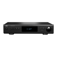
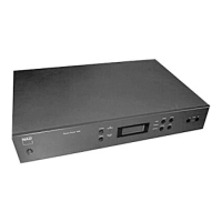
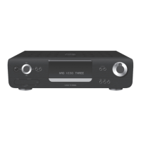
The NAD C427 is a Digital Media Tuner, designed for receiving both FM and AM radio broadcasts. This service manual provides comprehensive details for its maintenance, repair, and understanding of its internal workings.

Function Description

The NAD C427 primarily functions as a high-quality radio tuner, capable of receiving both FM and AM signals. It incorporates RDS Decode Sensitivity for FM, which allows it to display additional information broadcast by FM stations, such as station name, program type, and song title. The device is built around a main MCU (M30281FAHP) which handles overall control, and a VFD Driver MCU (PIC18F26K20) for managing the Vacuum Fluorescent Display (VFD). The tuner module itself is a KUANGXIN FM/AM/RDS MODULE (kst-mb114ma1-23), indicating a dedicated, integrated component for radio reception. Power is supplied by a main PSU providing +/-12V and +8V, and a standby PSU for low power consumption. The device features an encoder board for user input, a front panel with key and IR input, and an RS232 port for potential external control or diagnostics.

Important Technical Specifications

FM Section:

  • Usable Sensitivity (98 MHz): 10 dBu
  • Signal/Noise Ratio: 65 dB (Mono, IHF-WTD), 60 dB (Stereo, IHF-WTD)
  • Frequency Response: ±1.5 dB (20 Hz - 15 kHz, 60 dB)
  • Channel Separation (60 dBu): 33 dB (30 Hz), 40 dB (1 kHz), 32 dB (10 kHz)
  • Capture Ratio (40 dBu): 3 dB
  • AM Suppression: 50 dB (60 dBu, 100% Mod. FM, 30% Mod. AM)
  • Image Rejection (119.4 MHz): 70 dB
  • I.F. Rejection (10.7 MHz): 70 dB
  • Pilot Suppression (60 dBu): 60 dB
  • Total Harmonic Distortion (Mono): 0.4%
  • Total Harmonic Distortion (Stereo): 0.8%
  • Auto Search Sensitivity: 24 dBu
  • RDS Decode Sensitivity: 26 dBu

AM Section:

  • Usable Sensitivity (999/1000 Hz): 55 dB
  • Signal/Noise Ratio (5 mV in): 42 dB
  • Total Harmonic Distortion (5 mV in): 1.5%
  • IF Rejection (450 kHz): 40 dB
  • Image Rejection (F+2xIF): 28 dB
  • Selectivity: 20 dB
  • Loop Sensitivity (20dB S/N): 66 dB (999/1000 Hz, 603/600 Hz, 1404/1400 Hz)
  • Frequency Response (100 - 2.3 kHz, 5 mV): ±6 dB

The device operates with a crystal frequency of 18.432 MHz. Its power supply unit (PSU) is designed for low standby power consumption (<0.2W dissipation).

Usage Features

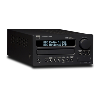
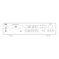
The NAD C427 is designed for straightforward operation, featuring a front panel with key and IR input for user interaction. An encoder board likely provides rotary control for tuning or menu navigation. The Vacuum Fluorescent Display (VFD) offers clear visual feedback of station information, settings, and RDS data. Connectivity includes FM and AM antenna inputs, as well as stereo RCA outputs (LO and RO) for connecting to an amplifier or receiver. An RS232 socket (D Connector 9) suggests the possibility of integration into a larger control system or for firmware updates/diagnostics. The presence of a USB connector (CON208) on the FPP board indicates potential for media playback from USB devices or for service-related functions. The device also includes a "Power ON" button and LED indicators (Red, Amber, Blue) for status.

Maintenance Features

The service manual provides detailed information crucial for maintenance and repair:

  • Wiring Diagram: Illustrates the interconnections between the FPP Board, Encoder Board, Main Board, PSU Board, and FM/AM Tuner. This is essential for troubleshooting connectivity issues.
  • Wiring Diagram Parts List: Specifies the cables used for internal connections, including their part numbers, descriptions (e.g., cable type, pin count, length), and remarks (e.g., "Tuner To Main Board").
  • Block Diagram: Offers a high-level overview of the system architecture, showing the main functional blocks like the Main MCU, VFD Driver MCU, FM/AM/RDS Module, and PSUs, along with their interfaces (SPI, I2C, GPIO, RDS DATA). This helps in understanding signal flow and isolating faulty sections.
  • Circuit Diagrams: Detailed schematics for the Main Board, FPP Board, FPP Encode Board, and SMPS Board, providing component-level information for diagnosis and repair.
  • PCB Layouts: Top and bottom layer views of the Main Board, FPP Board, FPP Encode Board, and SMPS Board, aiding in component identification and tracing circuits on the physical boards.
  • Electrical View Parts List: Comprehensive lists of all electrical components (diodes, transistors, ICs, resistors, capacitors, crystals, connectors) for each PCB, including part numbers, descriptions, and specifications. This is vital for sourcing replacement parts.
  • Exploded View and Parts List: Provides a visual breakdown of the device's mechanical assembly and a corresponding list of mechanical parts (fascia, lens, film, knobs, feet, chassis, brackets, panels, switches, display, screws, spacers). This is useful for disassembly, reassembly, and replacing structural or cosmetic components.

The inclusion of specific part numbers and detailed descriptions for each component, along with clear diagrams, makes the NAD C427 highly serviceable. The standby PSU's low power dissipation is also a maintenance-friendly feature, indicating efficient design and potentially longer component lifespan due to reduced heat.

NAD C427 Specifications

General IconGeneral
BrandNAD
ModelC427
CategoryCar Receiver
LanguageEnglish

Related product manuals