Do you have a question about the NAD C715 and is the answer not in the manual?
Describes hazards and precautions related to fire and shock.
Explains the meaning of graphic symbols used in the manual.
Provides guidance on installing the product correctly.
General guidelines for performing service safely and correctly.
Steps to perform an insulation check on the unit.
Precautions for handling sensitive electronic components.
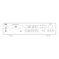
Technical specifications for the amplifier circuit.
Technical specifications for the tuner circuit.
Technical specifications for the AM tuner.
Technical specifications for the FM tuner.
Technical specifications for the CD player section.
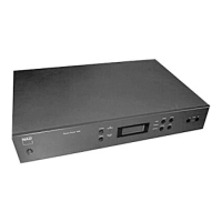
Dimensions and weight of the unit.
Technical specifications for the amplifier circuit.
Technical specifications for the tuner circuit.
Technical specifications for the AM tuner.
Technical specifications for the FM tuner.
Technical specifications for the DAB tuner.
Technical specifications for the CD player section.
Dimensions and weight of the unit.
Procedure for removing the top cover of the unit.
Procedure for removing the front panel of the unit.
List of parts for the exploded view of the C715AH.
List of screws used in the C715AH exploded view.
List of parts for the exploded view of the C715C.
List of screws used in the C715C exploded view.
List of parts for the exploded view of the C715DABC.
List of screws used in the C715DABC exploded view.
Details on integrated circuits and their pin functions.
Guide for diagnosing and resolving electrical issues.
Contains various circuit diagrams for the unit.
Overview of the internal architecture of the ST92F124V IC.
Shows the pin layout of the HY57V161610ET.
Describes the function of each pin on the HY57V161610ET.
Illustrates the functional blocks of the ISL1208 IC.
Details the function and purpose of each pin.
Shows the pin assignment for the LC72723M IC.
Depicts the internal structure and operations of the LC72723M.
Illustrates the logic functions of the M29W400D.
Shows the pin connections in the TSOP package.
Displays the internal functional blocks and connections.
Details pin layout and block diagram of the TC94A54MFG.
Shows the pin connections for TC9162/TC9163/TC9164 AN/AF.
Illustrates the overall architecture and modules of the TCC760.
Shows a sample circuit configuration for the TDA 7292.
Depicts the pin layout of the TDA 7292 IC.
Illustrates the pinout of the TDA 7313 IC.
Steps for troubleshooting power-related issues.
Steps for troubleshooting USB functionality.
Steps for troubleshooting DAB reception.
Troubleshooting for CD tray open/close problems.
Provides a high-level overview of the system's block diagram.
Parts list for the main PCB assembly.
| Frequency range | 80 - 22000 Hz |
|---|---|
| Audio formats supported | MP3 |
| Signal-to-Noise Ratio (SNR) | 95 dB |
| Total Harmonic Distortion (THD) | 0.15 % |
| Digital tuner | Yes |
| Supported radio bands | AM, FM |
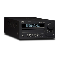
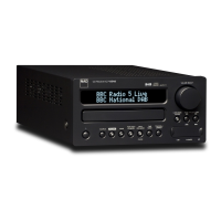
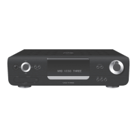
| Device type | Portable CD player |
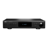
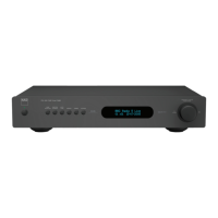
| Product color | Black |
| Disc loading type | Tray |
| Channel separation | 78 dB |
| Number of optical discs | 1 discs |
| Volume control | Rotary |
| Video in | 1 |
| Package depth | 116 mm |
| Package height | 362 mm |
| Package weight | 6000 g |
| Depth | 324 mm |
|---|---|
| Width | 213 mm |
| Height | 103 mm |
| Weight | 4500 g |