6 / 24
Mesurement Method
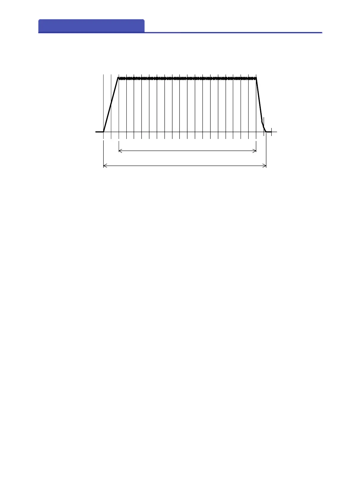
In the case of the following figure, regular current can be measured, supposing
it sets a start cycle as 1.5cyc and sets an end cycle as 10.0cyc for the measurement
section.
- When the crest value of measured current is extremely large , current overflow
may occur even if the current is within the measuring range.
- When measuring an inverter welding machine etc., and the load by the side of
secondary is extremely large, it may be unable to measure.
- Measurement of the tip voltage cannot be performed only by the tip voltage
detection cable. Please also connect CT cable simultaneously.
- When you connect the tip voltage detection cable, please do not connect AC
adapter and a USB cable. It cannot measure correctly.
-When it becomes an unusual welding form in AC measurement, it cannot
measure correctly.
-Measurement data may be unable to be saved when a measurement interval
is very short.
- Tip voltage of AC inverter welding machine cannot be measured.
- In DC measurement, the tip voltage cannot be measured correctly in the
sections (positive going transition of current, negative going transition of current,
a rise slope, down slope, etc.) which have change of current in a half-cycle.
0.5 1.0 1.5 2.0 2.5 3.0 3.5 4.0 4.5 5.0 5.5 6.0 6.5 7.0 7.5 8.0 8.5 9.0 9.5 10.0
start cycle
end cycle
mesurement time
welding time
11.010.5