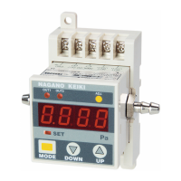
This document provides an instruction manual for the Nagano Keiki Co., Ltd. Model No. GS5 General Purpose Pressure Gauge. It outlines the basic operations, installation, usage, and maintenance procedures to ensure trouble-free and efficient operation.
The pressure gauge serves as a crucial instrument for measuring pressure, an important process variable alongside temperature and flow rate in manufacturing. Its primary function is to accurately indicate pressure, contributing to the overall efficiency and safety of industrial processes. The device is designed to meet the demands for higher performance and versatile functions required by advanced equipment and plant engineering technology.
Function Description
The core principle of operation for the GS5 pressure gauge relies on a Bourdon tube mechanism. When pressure is introduced through the socket, the Bourdon tube undergoes a displacement. This displacement is then transmitted via a rod to a movement mechanism, which scales the displacement and turns a pointer to indicate the measured pressure on a dial. This mechanical process ensures a direct and reliable reading of the pressure.
Usage Features
To ensure optimal performance and safety, several usage features and precautions are highlighted:
- Installation Orientation: The pressure gauge must be installed so that its scale plate is vertical. If vertical installation is not possible, the installation angle should be specified when ordering the device to ensure proper calibration and accuracy.
- Blow-out Disk: The pressure gauge is equipped with a blow-out disk located on its back. This disk is a safety feature designed to pop out and relieve internal pressure backward in the event of a Bourdon tube burst. When installing the gauge, it is crucial to leave adequate space (at least 10 mm) behind the blow-out disk to allow it to function properly. If installed before a panel, a hole of 25 mm or more in diameter should be made in the panel to accommodate the blow-out disk's operation. Failure to ensure proper blow-out disk function can lead to dangerous accidents, such as the window breaking.
- Leakage Prevention: For mounting threads, appropriate sealing methods are essential. If parallel threads are used, a suitable gasket should be employed. For tapered threads, sealing tape or similar materials should be wound around them. Using union nuts is recommended for parallel threads as they offer flexibility in changing the installation direction. When tightening union nuts, care must be taken not to apply excessive force to the pressure gauge, as this can distort the case and lead to measurement errors. A wrench should be applied to the appropriate positions of the pressure gauge during tightening.
- Head Difference in Liquid Measurement: In liquid measurement applications, the head difference between the pressure outlet port and the pressure gauge can significantly affect accuracy. For instance, installing a 0 to 0.1 MPa pressure gauge one meter higher than the pressure outlet to measure water pressure will result in a reading 0.01 MPa lower than the actual pressure, representing a 10% F.S. error. Conversely, if the gauge is one meter lower, it will read 10% higher. If the installation position is known, it is possible to pre-adjust the pointer to compensate for this estimated error. Pressure gauges with a zero-point adjusting pointer can be calibrated on-site after installation.
- Vibration Management: To prevent distortion of the pressure gauge and the transmission of equipment vibrations, flexible pressure pipes should be used. These pipes should be clamped to eliminate resonance. If the pressure gauge must be installed directly on a pressure pipe with vibrations, the riser length should be minimized, as a long riser can amplify vibrations.
- Heat Protection: Avoid installing the pressure gauge near boilers or in areas exposed to direct heat radiation. If such installation is unavoidable, a shielding plate or similar protective measure should be used to prevent direct exposure to heat.
- Maintenance Access: Installing a cock or valve at the inlet of the pressure gauge is recommended to facilitate easy and efficient maintenance.
- Fluid Temperature Management: If the fluid to be measured exceeds 80°C, it should not be led directly into the pressure gauge. A pipe siphon should be installed to lower the fluid temperature before it reaches the gauge.
- Steam Measurement: In steam measurement, condensate can form. The lead pipe should be tilted to prevent condensate collection, and a drain plug should be connected to the end of the lead pipe.
- Mechanical Vibrations: For installations in areas with mechanical vibrations, it is advisable to install a panel separate from the vibration source and mount the pressure gauge on it. Flexible copper pipes or similar materials should be used between the outlet port and the pressure gauge. If the lead pipe is made of rigid materials like steel or stainless steel, vibrations will transmit directly to the gauge, nullifying the purpose of separating it from the vibration source.
- Pressure Range Adherence: The pressure gauge should be used to measure pressures less than 3/4 to 2/3 of its full scale. Applying pressures exceeding the maximum (full scale value) can damage the Bourdon tube, potentially causing injury or damage to peripheral devices and equipment.
- Dismounting Procedure: When dismounting the pressure gauge, always reduce the pressure to zero (atmospheric pressure) first. It is critical to close the valve to prevent fluid from spouting out, which could lead to scalds or injuries.
- No Remodeling: The pressure gauge should not be remodeled, nor should additional functions be added to it.
- Blow-out Disk Integrity: The blow-out disk should not be glued or altered in any way. Any modification can impair its proper function, leading to dangerous accidents if the Bourdon tube bursts and the window breaks.
- Pressure Variance: If the fluid has significant pressure variance, the pressure gauge may become defective prematurely. Most issues arise from such pressure variances and mechanical vibrations. Restriction devices at the inlet or dampeners (variable restriction types) can be used to reduce pressure variances. When adjusting a dampener, close it fully and then open it gradually. The restriction should not be stopped down to the extent that the pointer completely stops shaking, as this makes it impossible to confirm accurate pressure readings. The restriction should be adjusted so that the pointer slightly shakes.
- Fluid Compatibility: The liquid-contacting parts of the GS5 pressure gauge are primarily made of brass and stainless steel. These materials are not suitable for all substances. For corrosive fluids, diaphragm-type gauges or other appropriate gauges should be selected. Using the GS5 with corrosive fluids can damage or burst the Bourdon tube, leading to fluid leakage and potential injury or damage.
- Oxygen Measurement: For measuring oxygen, an oil-free pressure gauge must be used. General-purpose gauges may contain oil, which can react with oxygen and cause fire or explosion.
- Safety Standards: Users should refer to JIS B7505-1 for detailed safety guidelines and ensure the gauge is used safely.
Maintenance Features
Regular inspection and maintenance are crucial for the longevity and accurate operation of the GS5 pressure gauge:
- Periodical Maintenance: Adhere to legal regulations and perform maintenance at least once a year.
- Replacement Criteria: If cracks are found in the cover glass or if the blow-out disk shows signs of deterioration, the pressure gauge must be replaced immediately. A damaged cover glass due to a burst Bourdon tube can lead to dangerous accidents.
- Performance Check: Dismount the pressure gauge from the site and check its indication, including hysteresis, using a pressure standard gauge (e.g., a weight-type or liquid column pressure gauge).
- Throttle Inspection: If the pressure gauge has a throttle, it may not read the zero point correctly, giving the impression that it is not properly zero-adjusted. Always dismount the throttle before checking the gauge.
- Ledger Management: For effective pressure gauge control, maintain a ledger that records information such as tag numbers (if applicable) and serial numbers. Periodical check records help track the accuracy tendency of the gauges. For example, if a gauge required a 0.5% zero-point correction in the maintenance before last, 1% in the last maintenance, and now needs 3%, it indicates an accelerated deterioration in accuracy. Ignoring such deterioration without adjustment can lead to failure. Periodical checks enable preliminary prediction, ensuring that pressure gauges are used under optimum conditions. If accelerated deterioration in accuracy is observed, contact the nearest dealer or office for repair service.
- Repair Restrictions: According to the Metric Law, certified instruments can only be repaired by authorized manufacturers or repairers. Zero-point adjustment is considered a repair and must be performed by an authorized manufacturer or repairer.
Troubleshooting
The manual includes a troubleshooting guide to address common issues:
- Pointer Does Not Move:
- Check if pressure is applied and if the valve is open. Possible causes include zeroed pressure (clogged pipe with foreign matters) or a closed valve. Countermeasures involve providing a filter for the pipe and opening the valve.
- Pointer Does Not Indicate Pressure:
- Check if fluid and ambient temperatures are within the operating range. Exceeded temperatures can cause issues. If the ambient temperature is too high, re-install the gauge in a different position. If the process fluid is hot, use a pipe siphon.
- Check for excessive vibrations. Vibrations can cause wear of the movement. Re-install the gauge in a different position.
- Check for excessive fluctuating pressure. This can also cause wear of the movement. Use a dampener.
- Slow Response:
- Check the viscosity of the process fluid and pipe thickness. If the fluid is too viscous or the pipe is too thin, use a thicker pipe.
- Check the degree of stopping down the dampener. If it's stopped down excessively, adjust the restrictions properly.
- Pointer Does Not Read Zero When Dismounted:
- Check for excessive pressure application. This can deform the Bourdon tube. Use a higher range pressure gauge or implement overpressure prevention.
- Check if the throttle is clogged. Clogging with foreign matters can occur. Provide the pipe with a filter.
- Check for excessive vibrations or fluctuating pressure. These can cause wear of the movement. Re-install the gauge in a different position or use a dampener.
- Pointer Indicates Over Scale Point:
- Check for excessive pressure application. This can deform the Bourdon tube. Use a higher range pressure gauge or implement overpressure prevention.
- Check if the pressure gauge was dropped or impacted. Impacts can cause the pointer to shift or deform the Bourdon tube. Be careful not to apply impacts to the gauge.