The GC31 Digital Pressure Gauge is a compact electronic instrument designed for precise pressure measurement and control, complying with EMC directives. This device offers a range of features for monitoring and managing pressure in various applications, utilizing both digital display and output signals.
Function Description
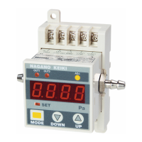
The primary function of the GC31 is to measure and display pressure digitally. It provides a clear 3 1/2 digit LED display for pressure readings and two red LEDs to indicate comparator output status. Beyond simple measurement, the device incorporates advanced control capabilities through its comparator outputs and an analog output.
The comparator function allows the device to trigger actions based on predefined pressure thresholds. It supports two main operation modes: hysteresis and window comparator. In hysteresis mode, the comparator operates with an upper limit (setting value A) and a dead band (setting value b), which can be configured independently for each of the two outputs. If a positive number (including 0) is selected for the dead band, the comparator operates with the setting value A as the upper limit. Conversely, selecting a negative number for the dead band sets the comparator to operate with setting value A as the lower limit. The dead band helps prevent chattering, especially when the set value is small, with a recommended minimum of 1%F.S. of the pressure range.
In window comparator mode, the device also uses two setting points (A and B) for each output, but the dead band is fixed at 1%F.S. for the direction in which the comparator turns OFF. This mode is suitable for applications requiring pressure monitoring within a specific range. Both comparator outputs (OUT1 and OUT2) operate in the same selected mode (hysteresis or window comparator).
Delay time settings are available for both ON and OFF operations of the comparator outputs, ranging from 0.00 to 2.00 seconds. These delays help prevent false triggers due to transient pressure fluctuations.
The device also provides an analog output (1-5 VDC) that scales proportionally to the measured pressure. This allows for integration with other control systems that require a continuous voltage signal representing the pressure. The analog output scaling can be adjusted to match specific pressure ranges to voltage outputs.
A "Loop check mode" is integrated to facilitate testing and simulation. In this mode, the displayed pressure value can be manually adjusted, and the comparator and analog outputs will respond accordingly, allowing users to verify wiring and output settings without applying actual pressure.
Usage Features
The GC31 offers a user-friendly interface with three keys: MODE, DOWN, and UP. These keys are used for navigating through different modes and adjusting settings.
- Measurement Mode: This is the default mode, displaying the current pressure, comparator output status, and analog output.
- Function Setting Mode: Accessed by holding the MODE key for 3 seconds, this mode allows configuration of various operational parameters:
- Comparator Operation Selection: Choose between hysteresis or window comparator modes.
- Display Selection: Select the pressure unit (Pa, kPa, or MPa) or enable display scaling for arbitrary pressure units.
- Display Scaling: When enabled, users can set the decimal point position and define minimum and maximum pressure values for the LED display. This feature allows the device to display pressure values in a custom scaled format, independent of the actual pressure range or analog output.
- Filter Selection: Five internal time constant filters (25ms, 250ms, 2.5s, 5s, 10s) are available to stabilize the display and outputs when pressure fluctuations are sharp or unstable. A "No filter" option is also available.
- Analog Output Scaling: Configure the pressure values corresponding to the 1VDC (zero point) and 5VDC (span point) of the analog output, expressed as a percentage of the full-scale pressure range.
- Comparator Setting Mode: Accessed by pressing the MODE key (release within 3 seconds) from measurement mode, this mode allows detailed configuration of the comparator outputs:
- Setting Point A and B: Define the pressure thresholds for comparator operation.
- Dead Band: Set the dead band for hysteresis mode.
- ON/OFF Delay Time: Configure the delay times for comparator activation and deactivation.
- Zero Point Adjustment Mode: By pressing MODE + UP keys for more than 3 seconds, users can perform an automatic zero adjustment after releasing pressure from the port. A successful adjustment is indicated by "AdJ" on the display.
- Peak Hold Display Mode: This mode allows the device to store and display the maximum (peak) and minimum (bottom) pressure levels applied to the port. These values are retained in internal memory until power is restored or manually reset.
- Key Lock Function: To prevent accidental changes to settings, a key lock function is available. Pressing MODE + DOWN keys in measurement mode activates the lock, indicated by "LoC". The same key combination unlocks the device, indicated by "UnL".
Maintenance Features
The GC31 is designed for reliability with no moving parts in its sensing element or circuit components, minimizing the need for frequent adjustments. However, regular checks are recommended due to potential aging effects.
- Biannual Regular Check: A biannual check is recommended to ensure optimal performance.
- Zero Point Adjustment: The zero point adjustment procedure can be performed as needed to maintain accuracy.
- Troubleshooting: The manual provides a comprehensive troubleshooting guide for common issues such as no display, no output, pressure display/output conflicts, and error messages. Error messages (e.g., FFF for upper limit, -FFF for lower limit, E-0 for zero point adjustment error, E1-/E-2/E12 for comparator overload) guide users to specific problems and recommended actions.
- Backup of Setting Values: The device incorporates an internal EEPROM, ensuring that all settings and the key lock state are retained even after power is turned off. However, peak and bottom hold values are not maintained and will reset upon power restoration.
- Noise Prevention: Recommendations are provided to prevent malfunctions due to electrical noise, including using a stable power source, keeping connection cables short, separating the device from noise sources, and connecting to an indoor distribution network free from overvoltage.
- Storage: Guidelines for proper storage are provided to prevent damage or malfunction, emphasizing avoidance of water, extreme temperatures, humidity, direct sunlight, dust, salt, corrosive air, vibration, shock, and chemicals.
- Physical Handling: Users are cautioned against disassembling or altering the device and are advised to contact the manufacturer for repairs. Care should be taken not to use sharp objects to press the keys to avoid damage to the panel. When mounting, ensure that excessive force is not applied to the resin body, and use seal tape to prevent leakage.