This installaon guide applies to EZvav digital
display wall sensors connected to EZvav
controllers.
For complete details, download IOM
“IOM-EZVAVINST” from Nailor website.
Choosing a sensor locaon
Install the sensor on an inside wall where it can sense the average
room temperature. Avoid locaons with direct sunlight, heat
sources, windows, air vents, and air circulaon obstrucons such
as curtains or furniture.
For models with moon sensing, see the topic on the following
page, Planning for moon sensing.
Rough-in preparaon
Complete rough-in wiring at each sensor locaon prior to sensor
installaon. This includes the following items:
• If required, install an appropriate backplate.
• Route an Ethernet connecng cable from the sensor to the
controller locaon.
• Maximum cable length is 75 feet (22.9 meters). Plenum-
rated preassembled cables are recommended.
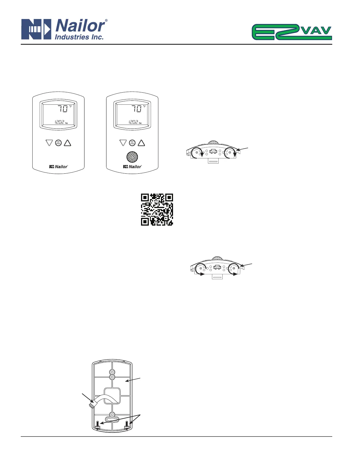
Mount the sensors
To install the sensor on a mounng base, do the following:
1. Turn the Allen screws in the base of the sensor clockwise unl
they clear the case. Swing the sensor away from the mounng
base to remove it.
2. Route the Ethernet cable through the mounng base.
3. Fasten the mounng base directly to a 2 x 4 inch (51 x 102
mm) outlet box or a backplate with the Allen screws toward
the oor.
4. Insert the Ethernet cable coming from the base into the sensor.
5. Place the top of the sensor over the top of the mounng base
and swing it down over the Allen screw brackets. Be careful
not to pinch any wiring.
6. Turn the Allen screws counterclockwise unl they back out of
the mounng base and engage the case of the sensor.
Operaon
The sensor will become operaonal as soon as it is connected to
an operaonal controller. See the following pages to change room
set points or congure a EZvav controller with the sensor.
Maintenance
Remove dust as necessary from holes in top and boom. Clean
the display with so, damp cloth and mild soap.
IOM-EZVAVQSIG
Date: 9-2015 Supersedes: NEW
Page 1 of 4
Quick Start Installation Guide – EZvav Sensors & Controllers
www.nailor.com
Turn screws clockwise to
remove sensor case from base.
Mounng
Base
Ethernet Connecng
Cable
Maximum 75 feet
(22.9 meters)
Allen
Screws
Nailor reserves the right to change any information concerning product or specification without notice or obligation.
Turn counterclockwise unl the
screws engage the case.
EZvav Sensors:
STE-8001W36
Digital Display
STE-8201W36
Digital Display with Occupancy Sensor