3/11 IOM-AECVAV
Nailor Industries Inc. reserves the right to change any information concerning product or specification without notice or obligation.
Page 2 of 10
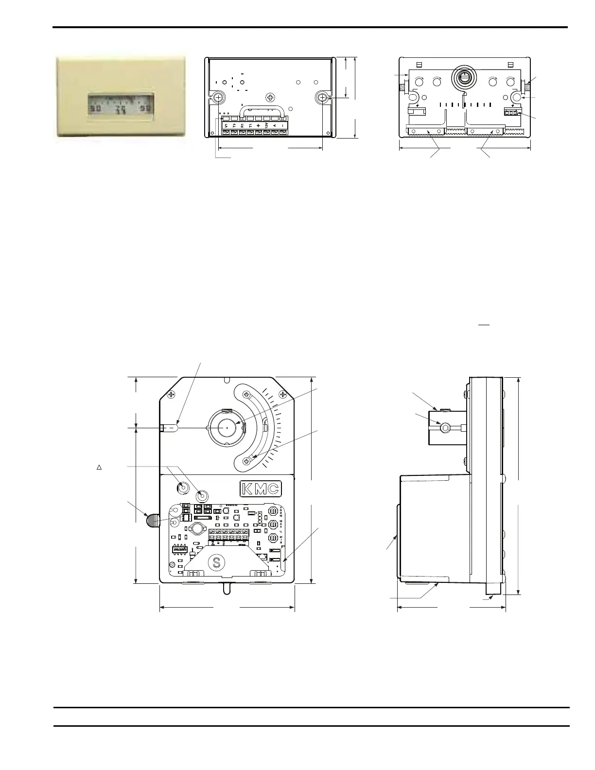
Figure 1. Thermostat Detail
Maintenance:
No routine maintenance is required. Each component’s design and material selection assures dependable long-term reliability and
performance. Careful installation will also enhance long term reliability and performance.
CSP-5002 DAMPER CONTROLLER/ACTUATOR
All Nailor standard right hand (and optional left hand) terminal units have a 1/2" (13), diameter drive shaft and a clockwise to close damper
rotation (Dual Duct Left Hand Deck CCW to close). Full damper shaft rotation is 45 or 90 degrees depending on model. The CSP-5002
should be mounted on the damper drive shaft so the actuator will stall at either end of the stroke to ensure tight shut-offs and full rotation.
Ensure the two jumpers are set for the correct damper rotation.
The CSP-5002 has a tri-color LED that indicates the current action of the damper: RED – Closing, GREEN – Opening, WHITE – Satisfied.
The CSP-5002 provides pressure independent VAV control for terminal unit primary valves. Primary air volume is monitored by the use of a
multi-point flow sensor located in the inlet duct. Differential pressure is measured by an onboard platinum transducer. The changes in the
inlet static pressure will vary the position of the inlet damper. Flow limit adjustments are made using a digital DC voltmeter at the thermostat.
The CSP-5002 is factory calibrated with VNOM adjustment centered for the enclosed voltage - airflow charts. Do not
adjust. Dampers are
always shipped in the full open position.
METER
TAPS
C
OVER MTG.
S
CREWS (2)
RETAINING
PINS (2)
S
CALE
P
LATE
(
°F OR °C)
70
KMC Controls
50 90
MAX/AUX
INCR
MIN
INCR
MIN
INCR
MAX
INCR
METERS
TAPS
METERS
TAPS
HEATING COOLING
V
V
B
ACK VIEW
3 1/4" (83)
2
9/16" (65)
6
3/64"
(
25)
1
31/32"
(
50)
WIRE CLAMP TERMINAL HEATING SLIDER
(WHERE APPLICABLE)
COOLING SLIDER
4" (102)
H
L
90
45
0
3 1/8" (79)
FIELD ADAPTABLE AUXILIARY
SWITCH NON-ROTATION SLOT
6 7/64"
(155)
1 1/2"
(38)
5 1/16"
(129)
DAMPER
SHAFT
ROTATION
JUMPERS
ADJUSTABLE
END STOPS
51" (13) DIA.
6 15/32"
(164)
DAMPER SHAFT
DRIVE HUB
ACESS
DOOR
GEAR DISENGAGE
MENT BUTTON
5/16-18 SET
SCREWS (2)
RED
GREEN
NON-ROTATION
TAB
5/8" (16) DIA.
WIRE ACCESS
SHUTTER
BUSINESS
P PORTS
3/16" (5) DIA. (2)
Figure 2. CSP-5002 Controller / Actuator
POWER REQUIREMENTS:
Controller / actuator / thermostat is 7VA plus any output loads for fan relays, heating contactors and control valves (assume 10 VA each).
Always switch control voltage off prior to disconnecting any wires from the controller.