3/11 IOM-AECVAV
Nailor Industries Inc. reserves the right to change any information concerning product or specification without notice or obligation.
Page 3 of 10
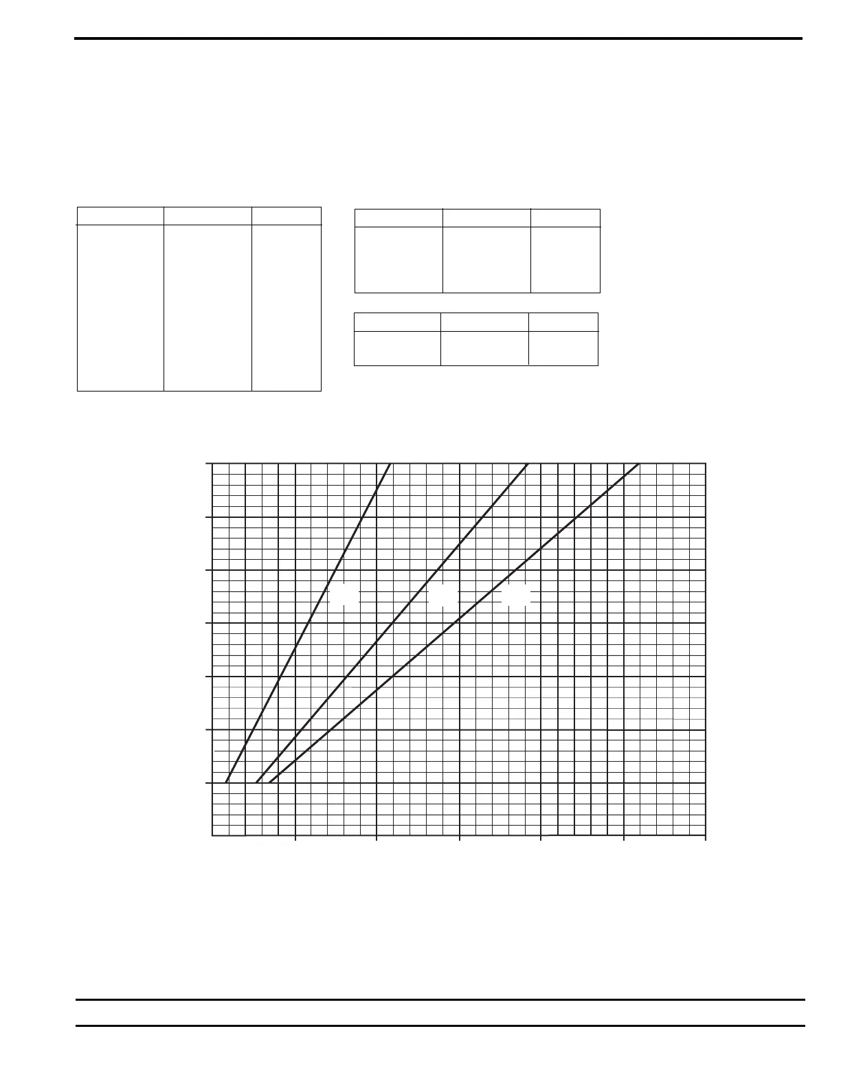
ANALOG CONTROL CALIBRATION CHARTS
VOLTAGE VS. AIRFLOW
When field adjustment or field calibration of the CTE-5100 series thermostats is necessary, desired limit control can be calculated using the
tables in Figure 3 and the following formulas, or the charts presented in Figures 4 through 8.
Formulas:
CFM = K (VDC - Offset) VDC = (CFM/K) + Offset
Follow the individual calibration procedure for the thermostat model(s) as required.
Inlet size K factor Offset
14 x 10 417 - 0.14
24 x 16 1250 - 0.07
Inlet size K factor Offset
4 in. Round 33 + 0.44
5 in. Round 55 + 0.02
6 in. Round 75 + 0.08
7 in. Round 115 - 0.19
8 in. Round 143 + 0.32
9 in. Round 175 + 0.10
10 in. Round 233 + 0.09
12 in. Round 357 - 0.04
14 in. Round 500 - 0.07
16 in. Round 625 - 0.25
Inlet size K factor Offset
12 in. Oval 333 - 0.22
14 in. Oval 417 - 0.47
16 in. Oval 588 + 0.05
18 in. Oval 759 - 0.27
Figure 3. Diamond Flow Sensor K Factors.
0
2.0
3.0
4.0
5.0
6.0
7.0
1.0
VOLTS, DC
0100200300400 600500
AIRFLOW,CFM
SIZE
4
SIZE
5
SIZE
6
Figure 4. Inlet Sizes 4, 5, 6 Round