3/03 IOM-DDTU
Installation and Operation Manual
Dual Duct Terminal Units
Nailor Industries Inc. reserves the right to change any information concerning product or specification without notice or obligation.
Page 1 of 4
Receiving Inspection
After unpacking the assembly check it for shipping damage. If any
shipping damage is found, report it immediately to the delivering
carrier. During unpacking and installation do not handle by the inlet
velocity sensor or the control package.
Supporting the Assembly
Dual duct units are designed to be independently supported. When
requested, unit is supplied with field mounted hanger brackets for
use with hanger rod up to 3/8" (9.5) dia. Hanger brackets should be
screwed into the top of the unit casing sides and/or the inlet and
outlet ends. Hanger straps may alternately be used and screwed
directly into the sides of the unit casing. Use the support method
prescribed for the rectangular duct in the job specifications.
Important: If unit is equipped with pneumatic controls, it should be
mounted right side up and level within ±10 degrees of horizontal
and parallel to the airflow. The terminal is marked with a label
stating "Top of Unit".The first letter in the model number indicates
control type (P is for pneumatic). If the unit is mounted upside
down, the controllers will have to be re-positioned, re-piped, and re-
calibrated. Analog control units (A-analog model number pre-fix)
may be installed in any orientation. Some Digital (DDC) controls (D-
digital model number pre-fix) are position sensitive dependent on
the airflow sensor transducer. Check with the controls manufacturer
for verification.
Duct Connections
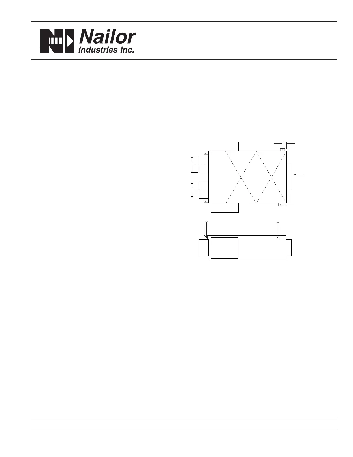
Slip each inlet duct over the inlet collar of the terminal. Fasten and
seal the connection as described in the job specification. The
diameter of the inlet duct "D" (see Figure 1) for round inlets (Models
3230 and 3240 with mixing attenuators) must be equal to the listed
size of the terminal; i.e., a duct that actually measures 8" (203)
must be fitted to a size 8 terminal inlet. The inlet collar is made 1/8"
(3) smaller than nominal duct size in order to fit inside the duct.
Model 3210 (no mixing attenuator) utilizes flat oval inlet collars on
unit sizes 12 through 16. They are undersized for flexible duct
connection. For hard inlet duct connections, refer to submittal
drawing for dimensional data. The supply ductwork should be
insulated up to the face of the terminal unit.
Important: Do not insert duct work inside the inlet collar of the
assembly. For optimum performance, 2 to 3 equivalent diameter
of straight duct should be installed prior to the inlet of the unit. All
ducts should be installed in accordance with SMACNA guidelines.
The outlet end of the terminal for models 3230 and 3240 is supplied
with a rectangular collar. A rectangular duct the size of the terminal
outlet should be attached.
Model 3210 is supplied with slip and drive duct connections. A
rectangular duct, the size of the terminal outlet should be installed.