Field Wiring
All field wiring must comply with NEC and local codes. Electrical,
control, and piping diagrams can be found on labels affixed to the
exterior/interior of the control enclosure box.
Control Start-up, Operation
Your local Nailor Representative can provide detailed information
about start-up and operating procedures for Nailor’s digital, analog,
and pneumatic controls. For specific information on controls
provided by other manufacturers, contact the specific
manufacturer’s local or national office. This applies whether the
controls were factory or field mounted.
Note: Digital controllers may use specific communication addresses
based on Building Management Systems Architecture and original
engineering drawings. Installing the terminal in a location other
than that noted on the label may result in excessive start-up labor.
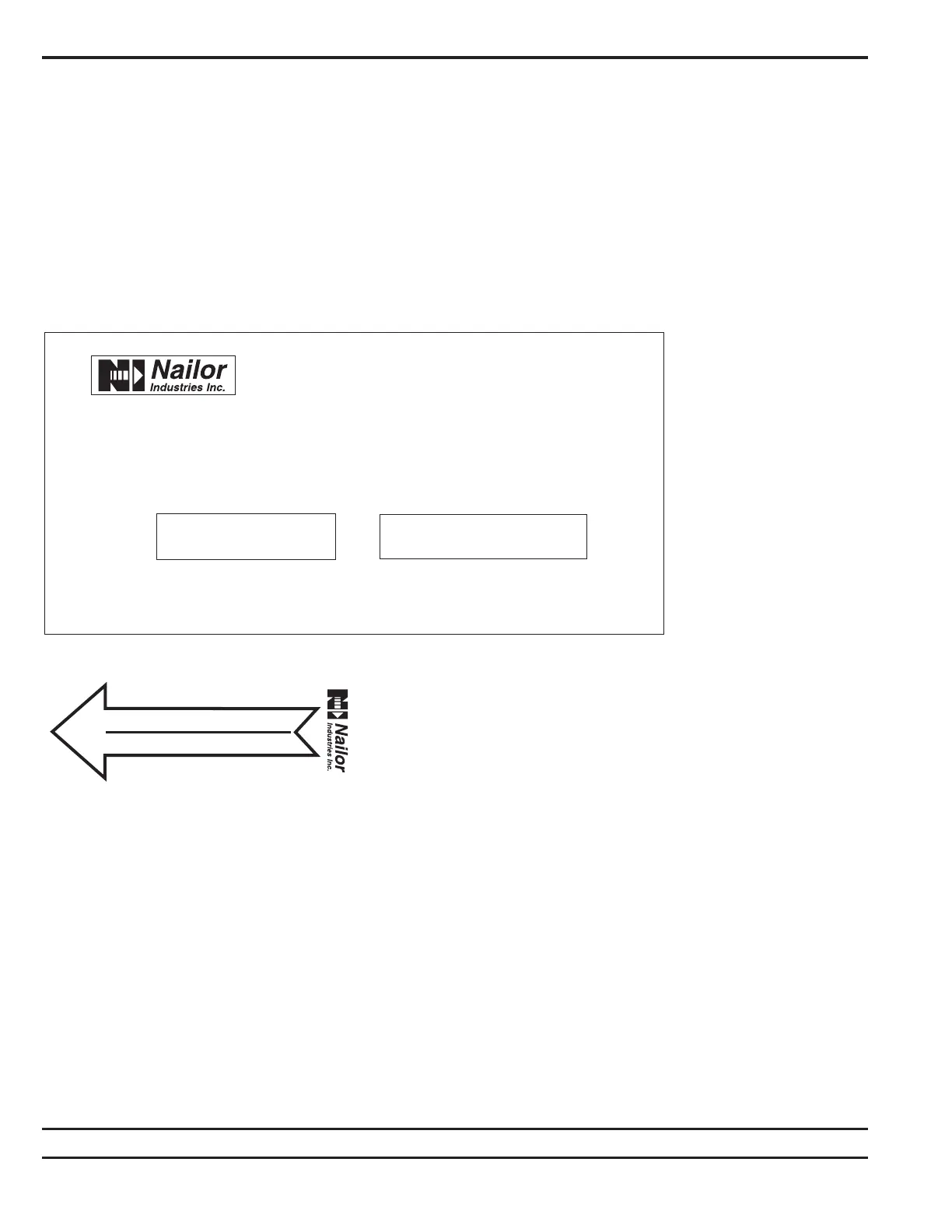
Labels
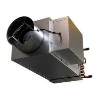
Dual duct terminal units are shipped from the factory with the
following information labels.
1) Nameplate Label – affixed to the air terminal casing on the
control mounting panel. Shows tagging information, serial number,
model number, size, cfm, etc.
Nameplate Label
DUAL DUCT
(UNITE TERMINALE @
TERMINAL UNIT
VENTILATEUR INTEGRÉ)
DATE
(DATE)
: 7-Nov-2001 SERIAL NO.
(NO. DE SÉRIE)
: 11673-2
MODEL (MODÈLE)
: P3230 TAG NO.
(NO. DÈTIQUETTE)
: JBH
UNIT SIZE-INLET SIZE : 8 VOLTAGE
(VOLTAGE)
:
(DIAMETRE D'ENTRÉE)
CONTROL VOLTAGE : 24
(
VOLTAGE DE CONTRÔLE)
CONTROL SEQUENCE : DP3
(SEQUENCE DE CONTRÔLE)
USE WIRE SUITABLE FOR AT LEAST 75
o
C
UTILISER UN FIL METALIQUE QUI CONVIENT AU MOIN 75
o
C
L1 IS COLOR CODED BLACK , L2 IS BLUE, L3 IS RED
L1 EST COLORÉ NOIRE, L2 EST BLUE , L3 EST ROUGE,
CONTROL WIRES CODED AS MARKED
LES FILS DE CONTRÔLE SON INDENTIFIÉE COMME MARQUE,
USE COPPER CONDUCTORS ONLY.
UTILISÉ DES CONDUCTEURS DE CUIVRE SEULEMENT.
USE CLASS K, RK1, A2D OR A6D FUSE OR HACR BREAKERS.
UTILISÉ DES FUSIBLES CLASS K, RK1, A2D, OU A6D OU HACR DISJONCTEURS.
CFM (MAX/MIN) : L/S (MAX/<MIN) :