48
Minimum gage for cord
IMPORTANT INSTRUCTIONS AND WARNING - Electric Devices
WARNING!
When using electric tools, basic safety precautions should always be followed to reduce the risk of fire,
electrical shock and personal injury.
Read all these instructions before operating this product and save these instructions.
1. In the event of a malfunction or breakdown, grounding provides a path of least resistance for electric
current to reduce the risk of electric shock. This tool is equipped with an electric cord with a grounding
conductor and a grounding plug. The plug must be plugged into a matching outlet that is properly installed
and grounded in accordance with all local codes and ordinances.
2.
Do not modify the plug provided if it dose not ¿t the outlet, A quali¿ed electrician must install the proper outlet.
3. Improper connection of the grounding conductor can result in electric shock. The grounding conductor
has an outer insulation that is green with or without yellow stripes. If repair or replacement of the electric
cord or plug is necessary, do not connect the grounding conductor to a live terminal.
4. Check with a qualified electrician or service person if the grounding instructions are not completely
understood, or if in doubt as to whether the tool is properly grounded.
5. Use only 3-wire extension cords that have 3-prong grounding plugs and 3-pole receptacles that accept the
power cord's plug.
6. Repair or replace a damaged or worn cord immediately.
7.
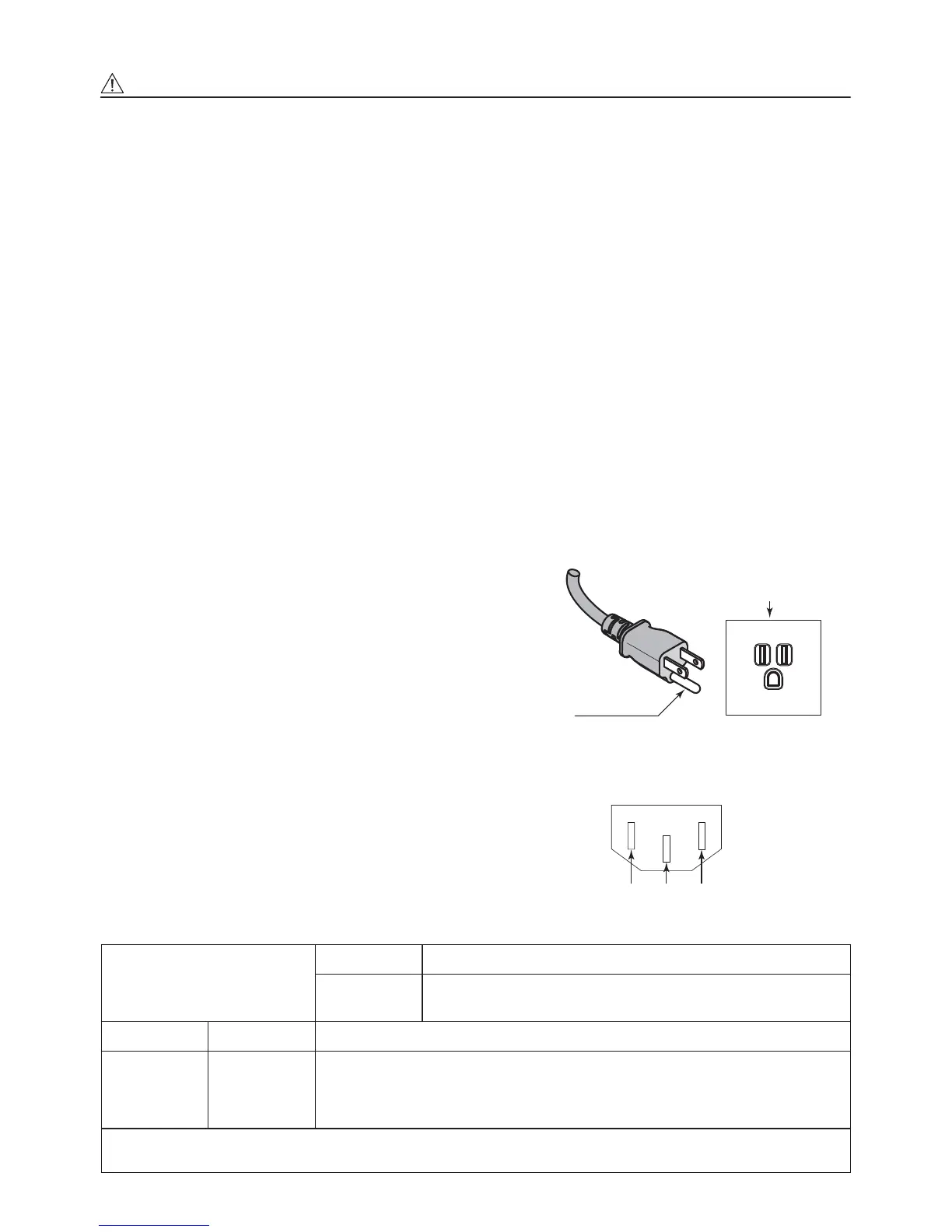
This tool must be used on a circuit that has an outlet that looks like the one illustrated in Sketch A in ¿gure (See
below) (
115
V). The tool has a grounding plug that looks like the plug illustrated in Sketch A in Figure (below).
8. FOR Installation in Machine Electrical Cabinet or when
wiring directly to machine internal power terminal strip:
1)
Please refer to the pin diagram below for the proper wiring
configuration. The plug shown is the female plug that
attaches to the E
3000
CONTROLLER main power inlet.
2)
Make sure you test each individual wire to verify proper
circuit prior to attaching any wire to the terminal block. Do
not assume wire colors are the same for all power cords.
9. Install an over current protective device of maximum 10
Amps on the E
3000 CONTROLLER main power circuit.
10. USE PROPER EXTENSION CORD. Make sure your
extension cord is in good condition. When using an
extension cord, be sure to use one heavy enough to carry
the current your product will draw.
An undersized cord will cause
a drop the line voltage
resulting in loss of power and overheating.
Table (below) shows the correct size to use depending on
cord length and nameplate ampere rating.
If in doubt, use the next heavier gage. The smaller the
gage number, the heavier the cord.
A. GROUNDING INSTRUCTIONS
Grounding Method
Grounding Pin
Cover Ground Outlet Box
A
L : Line
N : Neutral
E : Earth
LEN
Power Cord Connector
Ampere Rating
Volts Total length of cord
120V
240V
7.5m (25ft.)
15m (50ft.)
15m (50ft.)
30m (100ft.)
30m (100ft.)
60m (200ft.)
45m (150ft.)
90m (300ft.)
More Than Not More Than
0 6 18 16 16 14
6 10 18161412
10 12 16 16 14 12
12 16 14 12
Not Recommended
Only the applicable parts of the Table need to be included. For instance, a
120-volt product need include
the
240-volt heading.
 Loading...