6 StarLink
™
SLE-LTEVI-FIRE Commercial Series Dual-Path Alarm Communicator -- Installation Instructions
STEP 5: SIGNAL VERIFICATION
After triggering channels, use the StarLink radio Signal
Verification to ensure that the StarLink radio Network has
properly received the signals.
Verify Online: To verify that the signals have been
received by the StarLink radio GSM Network online, go
to www.NapcoNOC.com, log in with your Username and
Password, enter your Company ID number and the
StarLink GSM Radio Number, then click Signal Log.
IMPORTANT: Verify that the signals transmitted by the
StarLink radio have been properly received by your central
station before leaving the premises.
NOTE: This equipment has been tested and found to
comply with the limits for a Class B Unintentional Radiator,
pursuant to Part 15 of the FCC Rules. These limits are
designed to provide reasonable protection against harmful
interference in a residential installation. This equipment
generates, uses, and can radiate radio frequency energy
and, if not installed and used in accordance with the In-
struction Manual, may cause harmful interference to radio
communications. However, there is no guarantee that in-
terference will not occur in a particular installation. If this
equipment does cause harmful interference to radio or tele-
vision reception, which can be determined by turning the
equipment off and on, the user is encouraged to try to cor-
rect the interference by one of more of the following
measures: 1. Reorient or relocate the receiving antenna;
2. Increase the separation between the equipment and re-
ceiver; 3. Connect the equipment into an outlet on a circuit
different from that to which the receiver is connected; 4.
Consult the dealer or an experienced radio/TV technician
for help.
NAPCO GEMINI C-SERIES (GEMC)
CONTROL PANEL PROGRAMMING
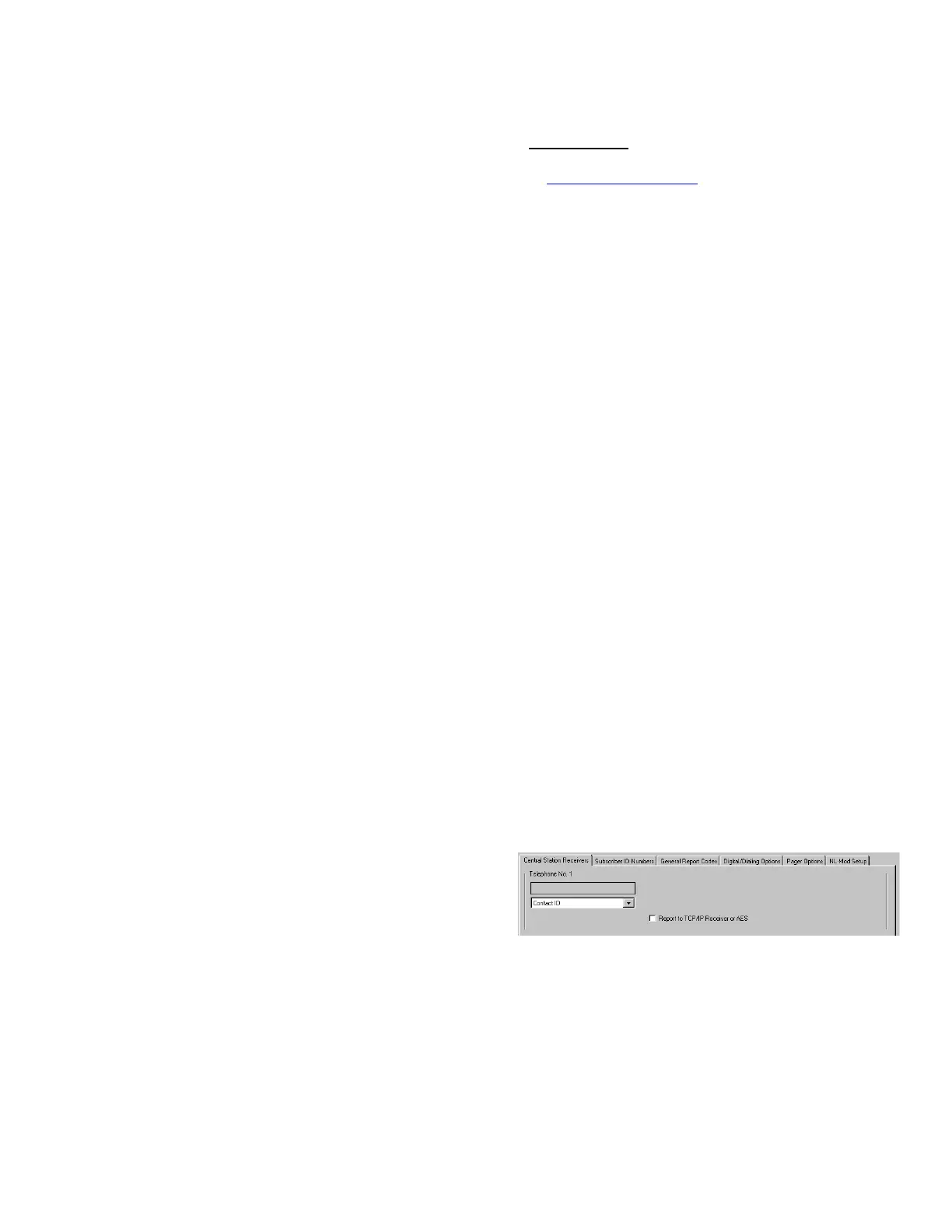
To program the central station receiver reporting format,
use PCD-Windows Quickloader download software. Open
the Digital Communications screen, Central Station Re-
ceivers tab, as shown in the following image:
A "Point ID" (also called "Contact ID") receiver format pro-
gramming example:
The radio can transmit to any central station capable of
receiving SIA Contact ID or 4/2 via DACR technology or
the DSC Sur-Gard Model System II or Sur-Gard System V
central station receivers, Bosch D6100IPV6 or Bosch
D6600 Receiver (with ITS-D6686 Ethernet Adapter) via
TCP/IP using standard line security.
Note: A receiver reporting format must be entered for
each telephone number used, but each telephone number
may be assigned a different format.
A fair amount of care may be required to mount the ra-
dio so as to achieve an optimal RF path. The installer
should spend as much time as needed to obtain the
highest signal level possible.
a. Before applying power, be sure to connect the
antenna. Temporarily connect power to the radio
from a fully charged 12V (4AH minimum) battery.
DO NOT mount the StarLink radio at this time. Press
Tamper switch to send a signal.
b. Position the unit in the desired mounting location,
with antenna oriented vertically. The signal strength
is displayed by the Green "Signal Strength LED" la-
beled "D3" (located at the lower right corner of the
PC board). The GSM radio tower signal strength
may fluctuate from day to day, therefore it is best to
try to find a mounting location where the LED pro-
vides a minimum of 4 blinks.
c. Once a location has been selected based on signal
coverage, permanently secure the unit using #8
screws (not supplied) in the two mounting holes.
WARNING: To ensure user safety and to satisfy FCC
RF exposure requirements, this unit must be installed so
that a minimum separation distance of 60cm (24") is al-
ways maintained between the antenna of the transmitting
device and nearby persons.
STEP 3: WIRING
22-gauge wire may be used if mounted up to 50 feet from
the control panel, and 18-gauge wire should be used for up
to 100 feet. Reference the wiring diagrams further in this
manual. See the section CONTROL PANEL PROGRAM-
MING further in this manual.
The wiring between the control panel and the StarLink ra-
dio is over several wires, as follows:
TB1: PWR
TB2: PWR GND (–)
TB21: N/C OUT1: Wired to the (+) of a zone dedi-
cated to monitoring the radio status. Should be pro-
grammed on Napco GEMC control panels as Monitor
or Supervisory Zone.
TELCO PRIMARY to FACP Telco 1 RJ-45 socket.
TELCO SECONDARY to FACP Telco 2 RJ-45 socket.
(Place JP1 shunt on bottom two pins)
Optional: Wire IN2 with a 10K EOLR in parallel with
the FACP trouble relay output Common and N/O (or in
series with Common and N/C).
Wiring Methods
Strip wire carefully to avoid exposed conductors after
installation, etc.)
Use of Listed wire, ensuring that all conductors are to be
insulated for the maximum voltage of any conductor in
the enclosure
All wiring methods must be performed in accordance
with NFPA70, Articles 725, and 800
STEP 4: APPLY POWER
Attach antennas before applying power !
Apply 12/24VDC to terminals 1 and 2.

 Loading...


