23
W415-0210 / R / 02.27.08
36
3
/4"
37
3
/4
"
52"
37
3
/
4
”
38
3
/
4
”
3”
14
1
/
2
”
63” (TOP EXIT)
42
1
/
4
” (REAR EXIT)
ENCLOSURE
TOP
FINISHING
MATERIAL
5
1
/
2
”
GAS
INLET
LOCATION
1
1
/
2
”
MAXIMUM
14”
MINIMUM
3
1
/
2
”
MAXIMUM
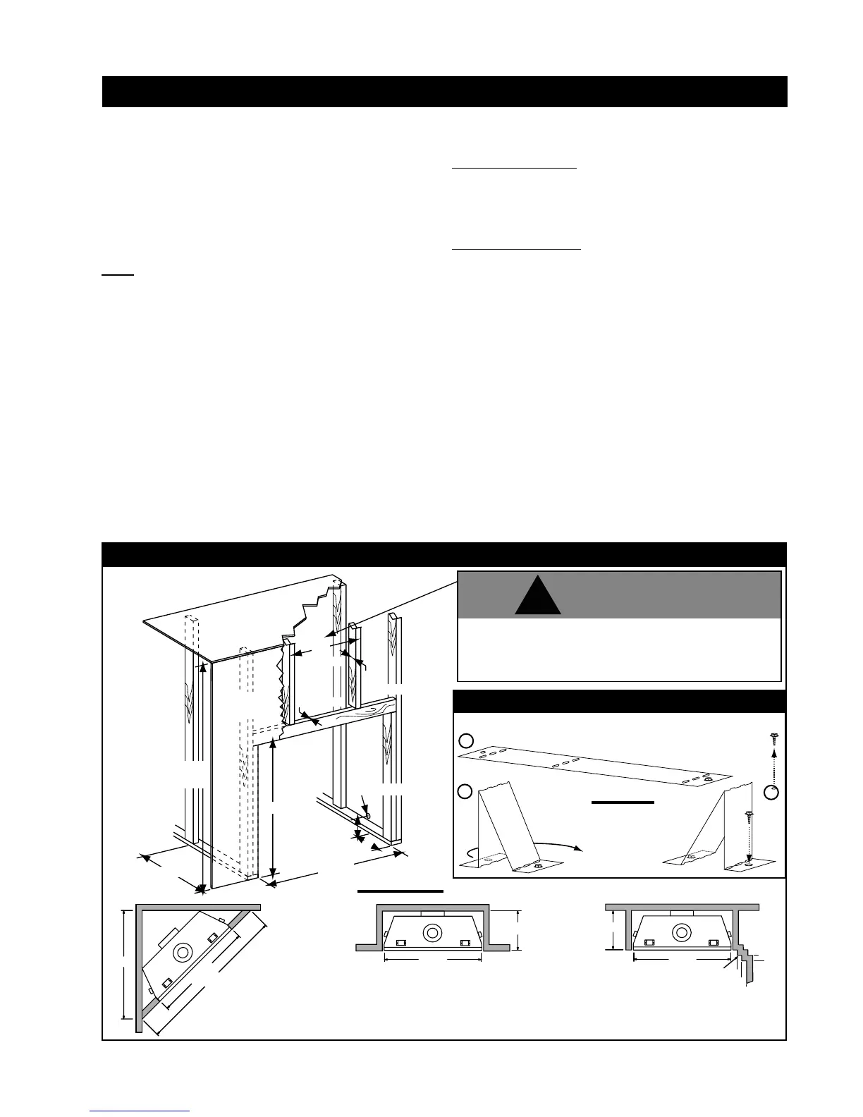
TOP EXIT INSTALLATION
SHOWN
For top exit applications: Do not build into this area - it
must be left clear to provide adequate clearance for the
vent. In this 14” wide area centred along the front of
the fireplace, no combustibles are allowed.
!
WARNING
It is best to frame your fi replace after it is positioned and the
vent system is installed. Frame to local building codes.
It is not necessary to install a hearth extension with this
fi replace system.
When roughing in the fireplace, raise the fireplace to
accommodate for the thickness of the fi nished fl oor materials,
i.e. tile, carpeting, hard wood, which if not planned for will
interfere with the opening of the lower access door and the
installation of many decorative fl ashing accessories.
Note: In order to avoid the possibility of exposed insulation
or vapour barrier coming in contact with the fi replace body,
it is recommended that the walls of the fi replace enclosure
be “fi nished” (ie: drywall/sheetrock), as you would fi nish any
other outside wall of a home. This will ensure that clearance
to combustibles is maintained within the cavity.
Combustible materials may be installed fl ush with the front of
the fi replace but must not cover any of the black face-areas
of the fi replace. Non-combustible material (brick, stone or
ceramic tile) may protrude in these areas.
FIGURE 45
Bend and secure the top stand-off(s) as illustrated:
A
B
C
STAND-OFF ASSEMBLY
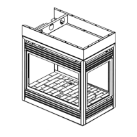
MINIMUM FRAMING DIMENSIONS
FIGURE 44 a-d
Combustion protrusions such as mantels and shelves may occur at or after a
minimum distance of 2" away from the side of the fi replace. Thereafter, the
depth of any protrusions must be equal to or less than the distance from the
side of the fi replace up to a depth of 6", after which no greater clearance than
6" is required. This can be considered a side wall with no length boundary.
GD36 FRAMING
37
3
/4"
14
1
/2"
OUTSIDE
CHASE
14
1
/2"
INSIDE
CHASE
37
3
/4"
4"
2"
SIDE
WALL
2"
4"
6"
PROTRUSION
* HORIZONTAL VENT SECTIONS - A minimum clearance of 1" at the
bottom and sides and 2" at the top of the vent pipe on all horizontal
runs to combustibles is required. Use fi restop spacer W010-1777
(supplied).
* VERTICAL VENT SECTIONS - A minimum of 1" all around the
vent pipe on all vertical runs to combustibles is required except
for clearances in fi replace enclosures. See "Minimum Enclosure
Clearances" section. Use firestop spacer W500-0096 (not
supplied).
Minimum clearance to combustible construction from
fi replace and vent surfaces:
Combustible Framing:
- 0" to stand-offs
- 1" to bottom and sides of the vent pipe*
- 2" to top of the vent pipe*
Combustible Finishing:
- 0" to rear
- 0" to front face top and sides
- 14 1/4" recessed depth
Rear Exit
- 42 1/4" to enclosure top from base of the unit
- 72" to ceiling from base of the unit
Top Exit
- 63" to enclosure top from base of the unit
- 72" to ceiling from base of the unit
http://www.northlineexpress.com
 Loading...