INSTALLATION
SECTION 2
7/03 2-11
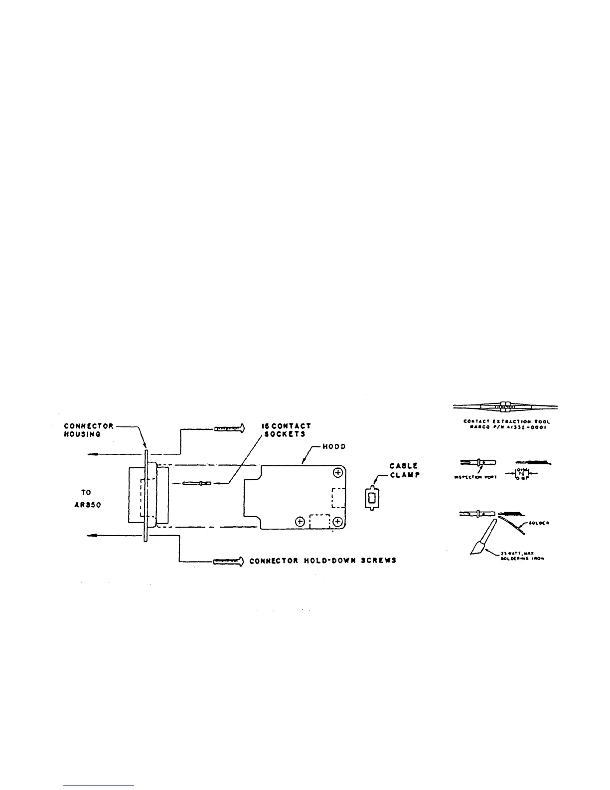
2.4.5 Interconnect Cable Fabrication
An interconnecting cable must be fabricated by the installing agency. Figure
2-4 shows the assembly of the AR850 connector P101.
1) Strip wire as shown in fig. 2-4. Maximum wire size is # 20 AWG.
2) Tin exposed lead. Be sure no individual wire strands are free!
3) Insert lead into socket until lead is visible at inspection port.
4) Heat socket and apply solder as shown until solder wicks into socket
cavity and becomes visible through inspection port.
5) Insert socket into connector housing until a "click" is heard or felt:
exert a slight pull on the wire to assure socket seating.
6) Final assembly :
a) Put hood in place around connector housing and cable.
b) Position cable clamp and hole filler.
c) Close the hood's lid and tighten 3 phillips screws.
d) Attach P101 to the AR850 with 2 connector hold-down screws.
Figure 2-5 shows the pin assignments to P101. Interconnect wiring diagrams
are provided in Section 2.4.7 APPENDIX.
FIGURE 2-4 P101 ASSEMBLY