,.ua,
and
a
warning
label
affixed
adjacent to the
switek. NARCQ's Remote Switch Kit contains
such a
switch
ad
warning
label.
See Section
5.
Equipment List for kit
paxt
number.
I
I.
The
final step of the installation
of
the
ELT
10
is
that
of
positioning
the
ELT
switch to
ARM.
This
compIetes
the
installation.
*
*
Should
an
installed checkout
be
desired, refer to
Section
I
I.
9.
MAINTENANCE
Every
three
msnths
or
after
108
hours
af
aircraf!
flight
time,
whichever eonles fint, the battery
pack
should
be
removed and inspected.
1.
Check
vbually
for
It%h@.
L
will
show
up
as
a
white
residue
w:hlch
nmdy
occurs
51%
around
$at-
tery
leads.
2.
Check visually for corrosion at battery terminals,
P.C:
board
and
components..
3.
Check
for
sewre battery leads.
General:
All
shop
maintenance
tests
should
be
perrwllneu
I41
a
screen
room.
Should the
E-LT
10
transmitter
be
found defective
by
a
NARC0
Authorized Repair Station,
a
new
replace-
ment
pretested printed circuit board can be ~btained
fram NARC0
(PM
01651-0101).
The hard
may
be
rerntsved
by:
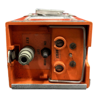
I,
Set
the
ON-OFF-ARM
switch
to
OFF.
2,
Extend the portabtt antenna.
3.
Unscrew the four screws that
hold
the
control head
to
the
battery
casing.
4.
Di'sconneft the battery
by
unsnapping the
snap-off
battery
pigtail
terminals
from
the
bottom
of
the
board.
5.
Unsofder the three
lead
connections. (See Figure
b~
6.
Remove the four screws that hold the
board
to the
control
head,
Reassemble
in
the
reverse order
of
the
above. Press the
reset button and then
set
the ON-OFF-ARM switch
to
ARM.
(Reinstall antenna as
shown
in
Rwre
4,)
(Note that the
battery
case
mates
the
control
hd
only
one
way.
match
the
screw holes.)
,
-
Page
11
 Loading...