MU
coax,
with
BNC
connector termination.
System
Weight:
Transmitker (including battery
pack,
portable
ao-
tenna, and mounting
bracket].
.
-3.5
pounds
(1.6
kg)
NARC0
Pixed
Antenna
(including
attached
coax
cable
and
connector)
,
.
.
.
. .
0.2
pounds
(91
grams)
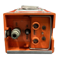
Size:
(exeluding antgnna)
8-13/16
x
2-9/16
x
3-1/8
(224
x
65
x
79mm)
(Seie
Figure71
8.
INSTAtLAT1ON
To insure the installer that
the
ELT
10
is
NOT
transmit-
ting
during installation, due to accidental activation, it
is
recommended that a nwby
VHF
receiver
be
turned
ON
and
tuned to
121.5
or
243.
MWz.
Th%
will allow
the
in~taller to hear the
signal
and switch the unit to
OFF.
The
ELT
is
approved
for
use in
the
Personnel
wnfig-
ymtion,
however, should the Unit be activated within
the
aircraft;
its
antenna, extended or not,
will
not
radiate
a
god
strong
signal,
Therefore to insure desired
safcty and best
signal
radiation, it
is
recommended that
the
ELT
10 be iastalled anly
in
the
ELT
(AP)
or
(AF)
cor6gurarion
,
.
.
thus install with
an
external
an-
tenna!
I.
The
instauation
must
be
performed in accordance
with
FAA
requiremeats
AC
43.13-2
or
other appli-
cable
airworthiness
authority directives.
2,
Mounting Location
ELT
CAP')
,
. .
.
install
iri
area
where unit
is
radily
~ccessibte for
portable
deployment. Fixed
an-
tenna
must
be
mounted outside
the
aircraft but
within
60
inches* of the transmitter.
ELT
(Am
.
.
.
the hation
of
the
ELT
is
impdrtant
for
maximum protection
in
the event of
a
damaged
aircraft
due to
an
emergency
landing.
Far
aft
such
as
the
central tailcone section
b
a
recom-
mended lacation.
Tf
possible,
snount
away
from
the
aimaft
skin
lo
reduce
the
effects
of
me
due
to
external sources.
DO
NOT
munt
the
unit
ia
the
bilge
as
plugged drain
holes
could
cause
totail sustained submersion
and
possible
unit
failure.
The
tixed
antenna
should
k
located
on the out~ide
of
the
akr&
as
dose
as
possible
to the
ELT
10.
Aaaw
slack
in
tbe
coax
cable
if
possible.
*
See
Figure
3