© National Instruments | 8-3
M Series User Manual
• Frequency Output
• PXI_STAR
• RTSI <0..7>
• Analog Comparison Event
• Change Detection Event
• DI Sample Clock* (di/SampleClock)
• DO Sample Clock* (do/SampleClock)
Note Signals with a * are inverted before being driven to a terminal; that is, these
signals are active low.
Using PFI Terminals as Static Digital I/Os
Each PFI can be individually configured as a static digital input or a static digital output. When
a terminal is used as a static digital input or output, it is called P1.x or P2.x. On the I/O connector,
each terminal is labeled PFI
x/P1.x or PFI x/P2.x.
In addition, M Series devices have up to 32 lines of bidirectional DIO signals.
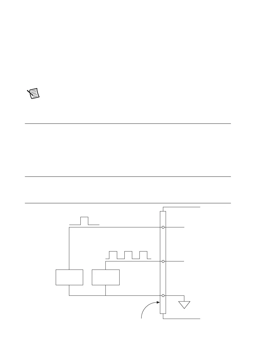
Connecting PFI Input Signals
All PFI input connections are referenced to D GND. Figure 8-2 shows this reference, and how
to connect an external PFI 0 source and an external PFI 2 source to two PFI terminals.
Figure 8-2. PFI Input Signals Connections
PFI 0
Source
PFI 2
Source
M Series Device
D GND
PFI 2
PFI 0
I/O Connector

 Loading...


