3-6 | ni.com
Chapter 3 Connector and LED Information
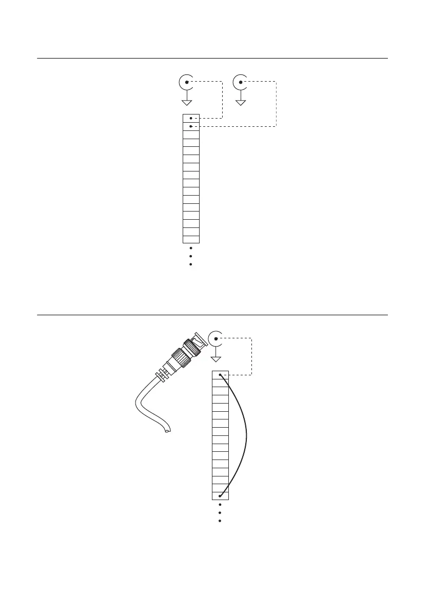
Figure 3-1. USER 1 and USER 2 BNC Connections
Figure 3-2 shows an example of how to use the USER 1 and USER 2 BNCs. To access the PFI 8
signal from a BNC, connect USER 1 on the screw terminal block to PFI 8 with a wire.
Figure 3-2. Connecting PFI 8 to USER 1 BNC
The designated space below each USER BNC is for marking or labeling signal names.
USER 2 BNC
D GND
USER 1
P0.6
P0.5
P0.4
D GND
P0.3
P0.2
P0.1
P0.0
D GND
+5 V
D GND
USER 2
PFI 8/P2.0
P0.7
D GND
Internal Connection
USER 1 BNC
D GND
Screw
Terminal
Block
BNC Cable
PFI 8
Signal
USER 1
P0.6
P0.5
P0.4
D GND
P0.3
P0.2
P0.1
P0.0
D GND
+5 V
D GND
USER 2
PFI 8/P2.0
P0.7
D GND
USER 1 BNC
D GND
Screw
Terminal
Block
Internal
Connection
Wire

 Loading...


