Appendix A Device-Specific Information
M Series User Manual A-58 ni.com
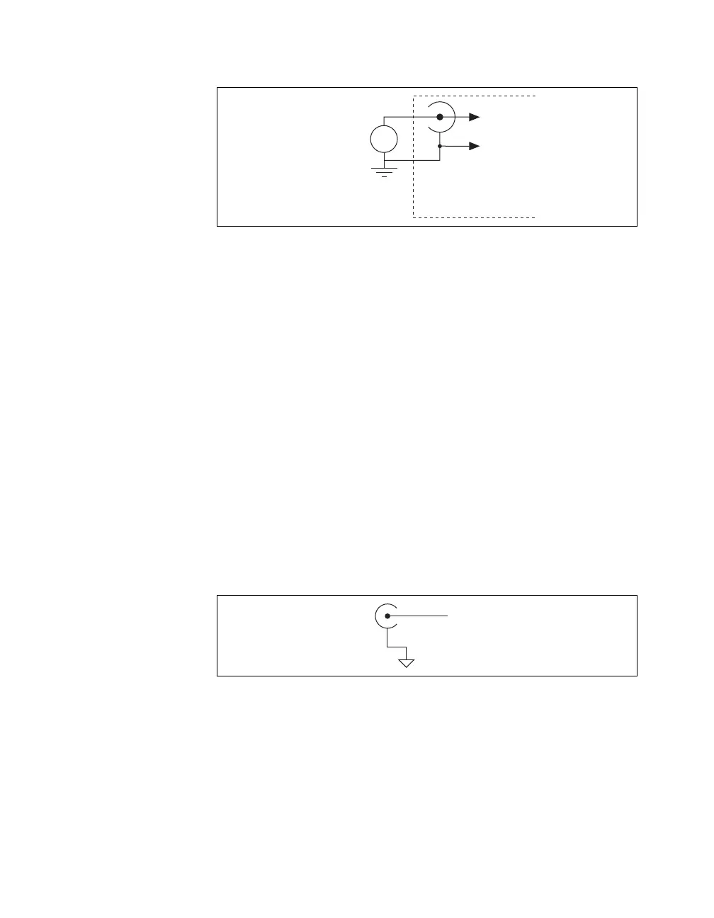
Figure A-22. Single-Ended Channels
When you set the source type to the GS position and software-configure the
device for single-ended input, each BNC connector provides access to
two single-ended channels, AI x and AI x+8. For example, the BNC
connector labeled AI 0 provides access to single-ended channels AI 0 and
AI 8, the BNC connector labeled AI 1 provides access to single-ended
channels AI 1 and AI 9, and so on. Up to 32 single-ended channels are
available in single-ended measurement modes.
For information on how to connect your single-ended signals, AI GND,
and/or AI SENSE, refer to the Connecting Analog Input Signals section of
Chapter 4, Analog Input. For a detailed description of each signal, refer to
the I/O Connector Signal Descriptions section of Chapter 3, Connector and
LED Information.
Analog Output
You can access analog output signals on the BNC connectors labeled AO 0
and AO 1. Figure A-23 shows the analog output circuitry on the USB-6229
BNC.
Figure A-23. Analog Output Circuitry
Refer to the Connecting Analog Output Signals section of Chapter 5,
Analog Output, for more information.
Ground Ref.
Source (GS)
AI x
+
–
AI x+8
USB-62xx BNC Device
AO
AO GND
 Loading...