NI 9751 User Manual | © National Instruments | 11
Solenoid Injector Operation
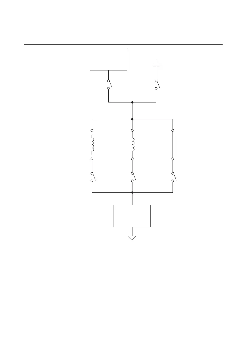
Figure 1 shows a representative simplified schematic that drives three solenoid injectors.
Figure 1. NI 9751 Simplified Schematic for Solenoid Injectors.
You can programmatically specify up to eight sequential drive phases within each solenoid
injection command pulse by using an 8-element IPhaseArray. Each phase is implemented
sequentially and can specify upper and lower current dithering setpoints, phase duration, and
high-voltage or battery-voltage drive circuit. Use the high-voltage drive circuit only when
necessary to conserve internal boost power supply energy and not overload it. A dual comparator
feedback circuit for upper and lower dithering thresholds controls the solenoid current. Other
current- and voltage- sensing circuits are used for fault detection.
Current Sense
& Comparator
Circuitry
Injector 1 Injector 2 Injector 3
+++
–––
CH1
Low-Side
Switch
CH2
Low-Side
Switch
CH3
Low-Side
Switch
Internal Boost
Power Supply
High-Side,
High-Voltage
Switch
High-Side,
Low-Voltage
Switch
BattV

 Loading...