12 | ni.com | NI 9751 User Manual
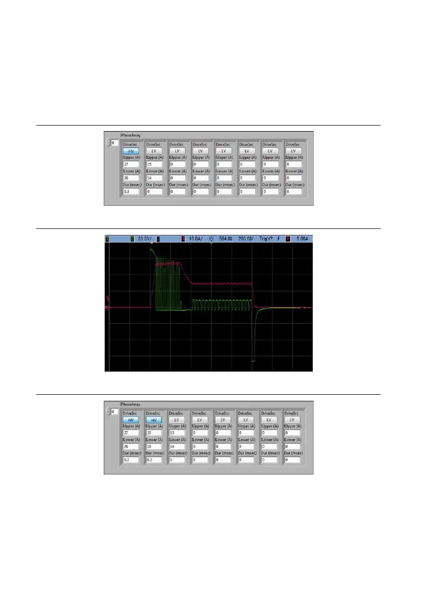
Figures 2 through 9, show oscilloscope images that demonstrate waveforms for four different
IPhaseArray configurations. Three of the examples show common direct injection waveforms.
The fourth waveform is not typical, but shows the flexibility of the IPhaseArray interface. The
total duration of the injection command is not determined by the total durations of the
IPhaseArray elements, but by the Boolean command delivered to the DI Driver FPGA Express
VI. If the Duration parameter of an IPhaseArray element is set to 0, the current levels for that
element are carried out for the remainder of the injection command.
Figure 2. Solenoid IPhaseArray Configuration Example 1
Figure 3. Current and Voltage Traces from Solenoid IPhaseArray Configuration Example 1
Figure 4. Solenoid IPhaseArray Configuration Example 2

 Loading...