NI 9751 User Manual | © National Instruments | 19
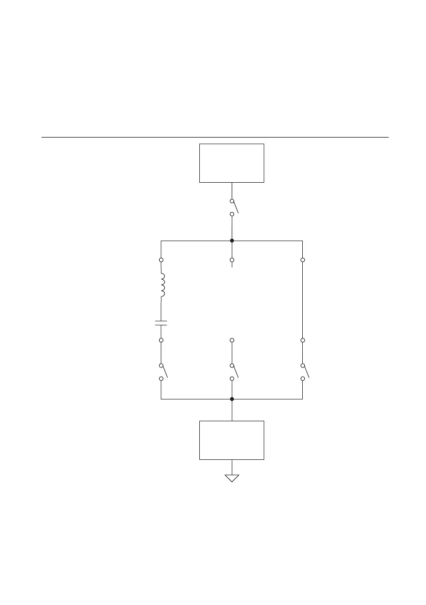
The NI 9751 can also operate inverted charge scheme piezo injectors. The PiezoInvert Boolean
determines the inverted piezo mode. The injector valve closes when the stack is charged and the
valve opens when the stack is discharged. Channel 1 can operate only a single piezo injector
when operated in inverted mode.You must leave Channel 2 disconnected and connect Channel 3
with a shorting jumper between the Inj+ and Inj- terminals. When you enable PiezoInvert mode,
the first four IPhaseArray elements are used for discharge and the last four elements are used for
charge. Figure 17 shows a representative simplified schematic that drives a single piezo injector
in inverted mode.
Figure 17. DI Driver Simplified Schematic for a Single Inverted Piezo Injector
Internal Boost
Power Supply
Current Sense
& Comparator
Circuitry
High-Side,
High-Voltage
Switch
47 µH
Inductor
ShortOpen
+++
–––
Piezo
Injector 1
CH1
Low-Side
Switch
CH2
Low-Side
Switch
CH3
Low-Side
Switch
 Loading...