24 | ni.com | NI 9751 User Manual
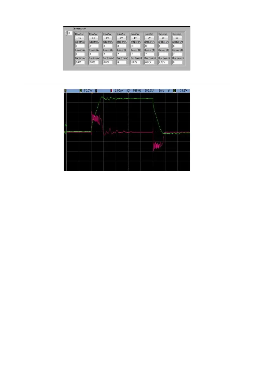
Figure 30. Piezo IPhaseArray Configuration Example 7
Figure 31. Current and Voltage Traces from Piezo IPhaseArray Configuration Example 7
HVTarget = 175 V.
Supported Injector Types
The NI 9751 can drive several different types of solenoid and piezo injectors, including gasoline
direct injectors. NI can help you determine the appropriate settings and operating limitations for
any type of injector at no cost if NI can reuse setup parameters for other custom projects. NI can
not verify injector operation on a fuel flow bench. Instead, NI will determine the optimum
software settings to achieve a specified current/voltage profile.
Injector Driver Circuit Faults and Protections
A short circuit in the NI 9751 might result in some scenarios. The NI 9751 detects each possible
short condition and reports critical faults. Each short circuit fault causes all power supply and
injection control operations to shut down automatically. You can re-enable the power supply and
injection control by manually clearing the faults with software.
Short Circuit Fault Conditions
INJ+ shorted to battery—This condition immediately causes a ShortCircuit critical fault.
Because current is flowing through the injector solenoid, the load inductance limits current rise
times and the NI 9751 typically detects the short at about 20 A if the channel is off and 45 A if
the channel is on.

 Loading...