© National Instruments | 3-3
NI cDAQ-9181/9184/9188/9191 User Manual
Analog Output Triggering Signals
Analog output supports two different triggering actions: AO Start Trigger and AO Pause
Trigger.
An analog or digital trigger can initiate these actions. Up to two C Series parallel digital input
modules can be used in any chassis slot to supply a digital trigger. An analog trigger can be
supplied by some C Series analog modules.
Refer to the AO Start Trigger Signal and AO Pause Trigger Signal sections for more information
about the analog output trigger signals.
Analog Output Timing Signals
The cDAQ chassis features the following AO (waveform generation) timing signals:
• AO Sample Clock Signal*
• AO Sample Clock Timebase Signal
• AO Start Trigger Signal*
• AO Pause Trigger Signal*
Signals with an * support digital filtering. Refer to the PFI Filters section of Chapter 4, Digital
Input/Output and PFI, for more information.
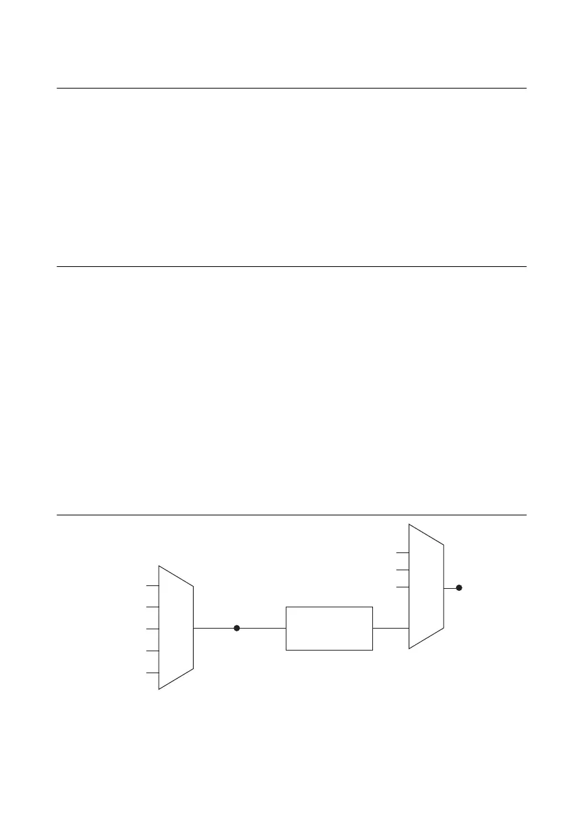
AO Sample Clock Signal
The AO sample clock (ao/SampleClock) signals when all the analog output channels in the task
update. AO Sample Clock can be generated from external or internal sources as shown in
Figure 3-1.
Figure 3-1. Analog Output Timing Options
Programmable
Clock
Divider
AO Sample Clock
Timebase
PFI
Analog Comparison Event
Ctr
n
Internal Output
AO Sample Clock
Analog Comparison
Event
20 MHz Timebase
80 MHz Timebase
PFI
100 kHz Timebase

 Loading...