© National Instruments | 3-27
NI 651x User Manual
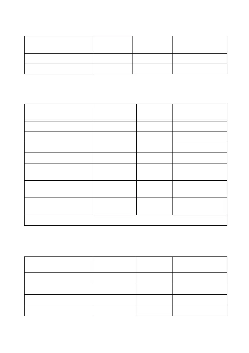
NI 6518 Signal Descriptions
NI 6519 Signal Descriptions
19 COM (VCC) Input Power line for all ports
5, 14, 28, 37 GND Input Ground for all ports
Table 3-9. NI 6518 Signal Descriptions
Pin Number Signal Name
Input or
Output
*
Signal Description
1, 2, 3, 4, 20, 21, 22, 23 P0.<0..7> Input Data lines for port 0
5, 6, 7, 8, 24, 25, 26, 27 P1.<0..7> Input Data lines for port 1
11, 12, 13, 14, 30, 31, 32, 33 P2.<0..7> Output Data lines for port 2
15, 16, 17, 18, 34, 35, 36, 37 P3.<0..7> Output Data lines for port 3
9 IN.COM Input Common line for all
input channels
10, 28, 29 VCC Input Power lines for all
ports
19 OUT.COM
(GND)
Input Ground for all output
channels
* The NI 6518 inputs are isolated from the outputs.
Table 3-10. NI 6519 Signal Descriptions
Pin Number Signal Name
Input or
Output
*
Signal Description
1, 2, 3, 4, 20, 21, 22, 23 P0.<0..7> Input Data lines for port 0
5, 6, 7, 8, 24, 25, 26, 27 P1.<0..7> Input Data lines for port 1
11, 12, 13, 14, 30, 31, 32, 33 P2.<0..7> Output Data lines for port 2
15, 16, 17, 18, 34, 35, 36, 37 P3.<0..7> Output Data lines for port 3
Table 3-8. NI 6517 Signal Descriptions (Continued)
Pin Number Signal Name
Input or
Output
Signal Description

 Loading...


