Table 7. 1 µA and 10 µA Current Output and Measurement Verification
Level
Range
Limit
Range and
Limit
Shunt Test
Point
As-Found
Measurement Test
Limit (% of Current +
Offset)
As-Left
Measurement Test
Limit (% of Current +
Offset)
6 V 1 µA 1 MΩ -0.9 V 0.022% + 40 pA 0.013% + 25 pA
0.9 V
60 V 10 µA -9 V 0.022% + 300 pA 0.013% + 200 pA
9 V
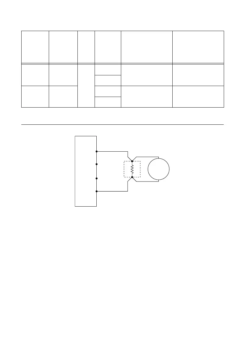
1. Make the necessary connections for this procedure, as shown in the following figure:
Figure 6. Current Connection Diagram, Part 1
NI-DCPower Device
Sense LO
Sense HI
HI
LO
+
–
Precision
Shunt
DMM
Voltage
Mode
2. Set the niDCPower Output Function property or NIDCPOWER_OUTPUT_FUNCTION
attribute to DC Voltage for the PXIe-4139.
3. Set the first specified level range, limit range, and limit on the PXIe-4139.
4. Measure the internal device temperature and perform self-calibration if necessary.
a) If the internal device temperature exceeds T
cal
±1 °C, wait up to five minutes for the
temperature to stabilize to within T
cal
±1 °C.
b) If after five minutes the stable temperature still exceeds T
cal
±1 °C, call the self-
calibration VI or function.
5. Set the level on the PXIe-4139 to the first specified test point.
Complete the following four steps within 5 minutes or less of completing step 4 in order
to ensure the internal device temperature remains stable.
6. Calculate the current through the shunt by completing the following steps.
a) Take a voltage measurement across the shunt using the DMM.
b) Divide the voltage measurement by the calibrated value of the shunt.
c) Record the calculated value as DMM Measured Current.
NI PXIe-4139 Calibration Procedure | © National Instruments | 13

 Loading...


