Table 8. 100 µA to 100 mA Current Output and Measurement Verification
Level Range Limit
Range and
Limit
Test Point As-Found
Measurement Test
Limit (% of Current +
Offset)
As-Left Measurement
Test Limit (% of
Current + Offset)
100 µA 6 V -100 µA 0.022% + 2 nA 0.013% + 1.5 nA
100 µA
1 mA 6 V -1 mA 0.022% + 20 nA 0.013% + 15 nA
1 mA
10 mA 6 V -10 mA 0.022% + 200 nA 0.013% + 150 nA
10 mA
100 mA 6 V -100 mA 0.022% + 2 μA 0.013% + 1.5 μA
100 mA
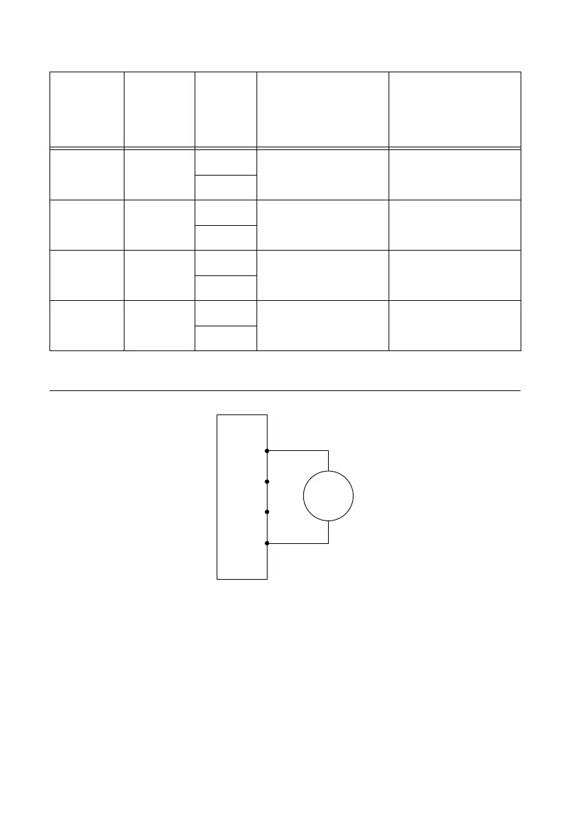
1. Make the necessary connections for this procedure, as shown in the following figure:
Figure 8. Current Verification Connection Diagram
NI-DCPower Device
Sense LO
Sense HI
HI
LO
DMM
Current
Mode
+
–
2. Set the niDCPower Output Function property or NIDCPOWER_OUTPUT_FUNCTION
attribute to DC Current for the PXIe-4139.
3. Set the first specified level range, limit range, and limit on the PXIe-4139.
4. Measure the internal device temperature and perform self-calibration if necessary.
a) If the internal device temperature exceeds T
cal
±1 °C, wait up to five minutes for the
temperature to stabilize to within T
cal
±1 °C.
b) If after five minutes the stable temperature still exceeds T
cal
±1 °C, call the self-
calibration VI or function.
5. Set the level on the PXIe-4139 to the first specified test point.
NI PXIe-4139 Calibration Procedure | © National Instruments | 15

 Loading...


