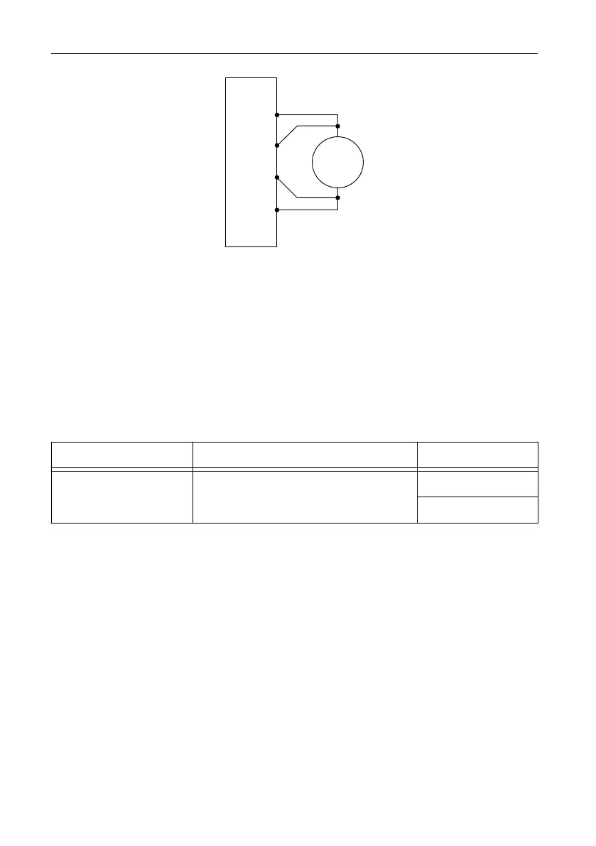
Figure 10. Voltage Verification or Adjustment Connection Diagram
DMM
Voltage
Mode
+
–
NI-DCPower Device
Sense LO
Sense HI
HI
LO
2. Set the niDCPower Sense property or NIDCPOWER_ATTR_SENSE attribute to Local.
3. Set the niDCPower Output Function property or NIDCPOWER_OUTPUT_FUNCTION
attribute to DC Voltage for the PXIe-4139.
Adjusting Voltage Output and Measurement
Compare a set of measured currents reported by the PXIe-4139 to the currents measured by a
DMM.
Refer to the following table as you complete the following steps:
Table 10. Voltage Output and Measurement Adjustment
Level Range Limit Range and Limit Test Point
6 V 100 mA 5 V
-5 V
1. Set the first specified level range, limit range, and limit on the PXIe-4139.
2. Set the level on the PXIe-4139 to the first specified test point.
3. Take a voltage measurement using the DMM.
4. Store the value from the previous step to use as an input for the niDCPower Cal Adjust
VI or function called in the following steps.
5. If more than one test point per level range is specified, repeat the previous steps for each
test point, from setting the level to the test point on the PXIe-4139 up to this step.
6. Update the output calibration constants by configuring and calling the niDCPower Cal
Adjust Voltage Level VI or niDCPower_CalAdjustVoltageLevel function.
a) Input the DMM measurements as the measured outputs.
b) Input the test points as the requested outputs.
c) Input the specified level range as the range.
NI PXIe-4139 Calibration Procedure | © National Instruments | 19

 Loading...


