8. Update the output calibration constants by configuring and calling the niDCPower Cal
Adjust Current Limit VI or niDCPower_CalAdjustCurrentLimit function.
a) Input the calculated shunt current measurements as the measured outputs.
b) Input the test points as the requested outputs.
c) Input the specified level range as the range.
9. If more than one level range is specified, repeat the previous steps using the values
specified in each level range.
Adjusting 1 A and 3 A Current Output and Measurement
Compare a set of measured currents reported by the PXIe-4139 to the currents measured by a
DMM.
Complete this procedure only after successfully completing all previous adjustment
procedures. Adjust ranges in the specified order.
Refer to the following table as you complete the following steps.
Table 12. 1 A and 3 A Current Output and Measurement Adjustment
Level Range Limit Range and Limit Shunt Test Point
1 A 6 V 1 Ω 1 A
-1 A
3 A 6 V 333 mΩ 3 A
-3 A
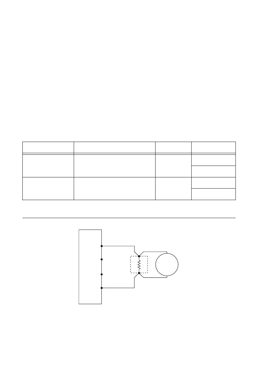
1. Make the necessary connections for this procedure, as shown in the following figure:
Figure 12. Current Verification Connection Diagram
NI-DCPower Device
Sense LO
Sense HI
HI
LO
+
–
Precision
Shunt
DMM
Voltage
Mode
2. Set the niDCPower Output Function property or NIDCPOWER_OUTPUT_FUNCTION
attribute to DC Current for the PXIe-4139.
3. Set the first specified level range, limit range, and limit on the PXIe-4139.
NI PXIe-4139 Calibration Procedure | © National Instruments | 21

 Loading...


