NI Digital Waveform Generator/Analyzer Guide 18 ni.com
Note Whether you use NI cables and accessories or design your
own, you should properly terminate cables to avoid improper
measurements due to signal reflections, overshoot, and undershoot.
Refer to the NI Digital Waveform Generator/Analyzer Help for more
information about signal termination.
Wiring for Common Measurements
Dynamic generation and dynamic acquisition are two categories of
applications that you can create for NI digital waveform generator/analyzers.
This section provides information on the general wiring considerations for
each type of application. Both examples use the NI CB-2162 for signal
termination.
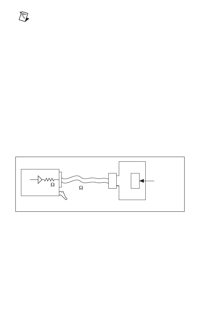
Dynamic Generation
When performing dynamic generation, an NI digital waveform
generator/analyzer generates data through a matched impedance system that
consists of a 50 Ω output impedance, a 50 Ω cable, and a 50 Ω accessory.
Figure 9 shows a diagram of such a system, using the NI 655x as an example.
Depending on the loading of the peripheral device, you may need additional
parallel termination resistance at the destination for optimal signal quality.
Refer to the NI Digital Waveform Generator/Analyzer Help for more
information about signal termination.
Figure 9. Dynamic Generation Functional Diagram
Dynamic Acquisition
When performing dynamic acquisition with the NI 654x/655x, the source
generating the signals needs a matched source impedance as close to 50
Ω as
possible to minimize signal reflections and maintain optimal signal quality.
Figure 10 shows a diagram of a dynamic acquisition system using the
NI 655x as an example.
NI 655
X
NI CB-2162
Peripheral
Device
50 Cable
50

 Loading...