Chapter 2 Theory of Operation
PCI E Series RLPM 2-14
©
National Instruments Corporation
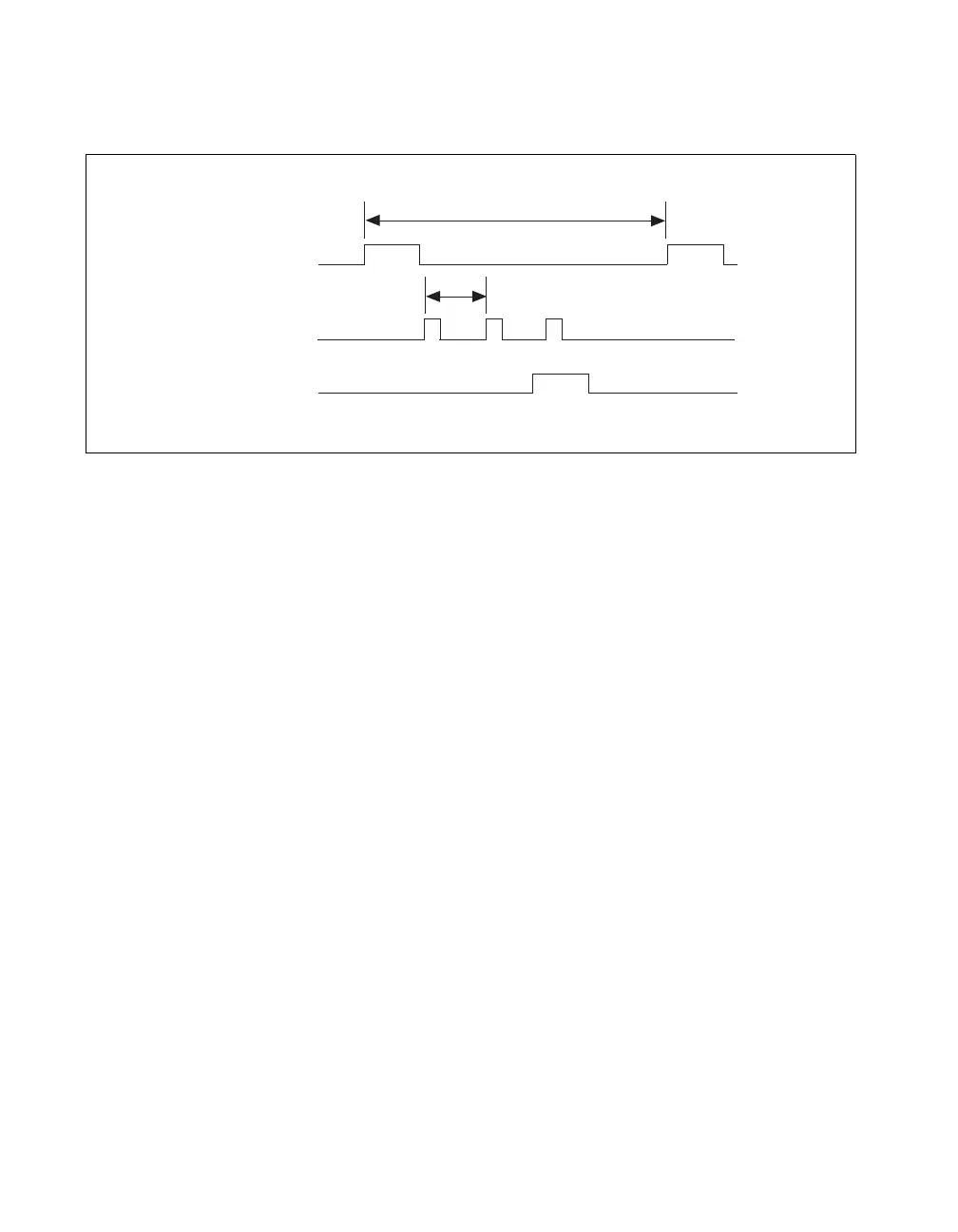
Figure 2-9 shows the timing for each scan in Example 1.
Figure 2-9. Timing of Scan in Example 1
The START pulse starts each scan. The first CONVERT pulse samples
channel 0, the second CONVERT pulse samples channel 5, and the third
CONVERT pulse samples channel 3. The STOP pulse ends the scan.
Example 1 allows you to sample all three channels at a rate of 10 kS/s per
channel (100 µs sample interval period). To achieve different rates for
different channels, you must do multirate scanning.
Multirate Scanning without Using Ghost
Example 2: To sample channel 0 at 10 kS/s and channel 1 at 5 kS/s, both at
gain 1 with 50 scans, program the configuration memory as follows:
1. Channel 0, gain 1
2. Channel 1, gain 1, last channel
3. Channel 0, gain 1, last channel
100 µs
10 µs
Channel 0 Channel 5
Channel 3
START
(TC of SI)
STOP
(last channel
or DIV TC)
CONVERT

 Loading...