© National Instruments | B-33
M Series User Manual
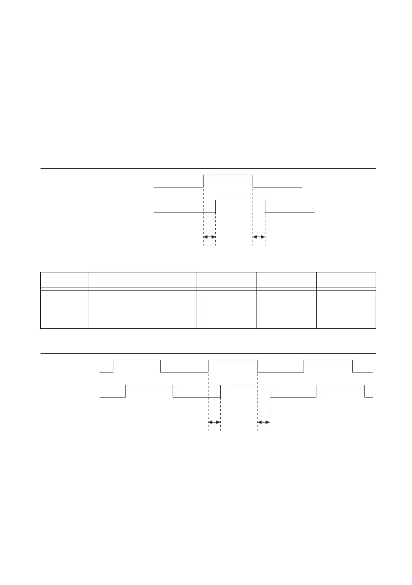
Selected Gate and Selected Source Delays
Tables B-27 and B-28 show the timing for the Selected Source and Selected Gate internal
signals.
Selected Source is used to clock the 32-bit counter. Selected Gate drives the Gate Logic, which
generates the Counter Enable signal.
All internal counter timing is referenced to these two signals. Any internal signal refers to signals
with _i from the previous table or signals coming from another subsystem inside the M Series
device. It does not include internal timebases or the PXI_CLK10.
Figure B-43. Selected Gate Delays Timing Diagram
Figure B-44. Selected Source Delays Timing Diagram
Table B-27. Selected Gate Delays Timing
Time From To Min (ns) Max (ns)
t
2
PFI_i, RTSI_i,
PXI_STAR_i,
or any internal signal
Selected Gate 1.0 6.0
t
2
t
2
PFI_i, RTSI_i,
or PXI_STAR_i
Selected_Gate
t
3
t
3
PFI_i, RTSI_i,
or PXI_STAR_i
Selected_Source

 Loading...


