Chapter 3 Signal Connections
NI 660x User Manual 3-20 ni.com
Crosstalk
Crosstalk mainly occurs when the capacitance between lines in a cable
induces a smaller transition on another line. Figure 3-9 shows an example
of crosstalk.
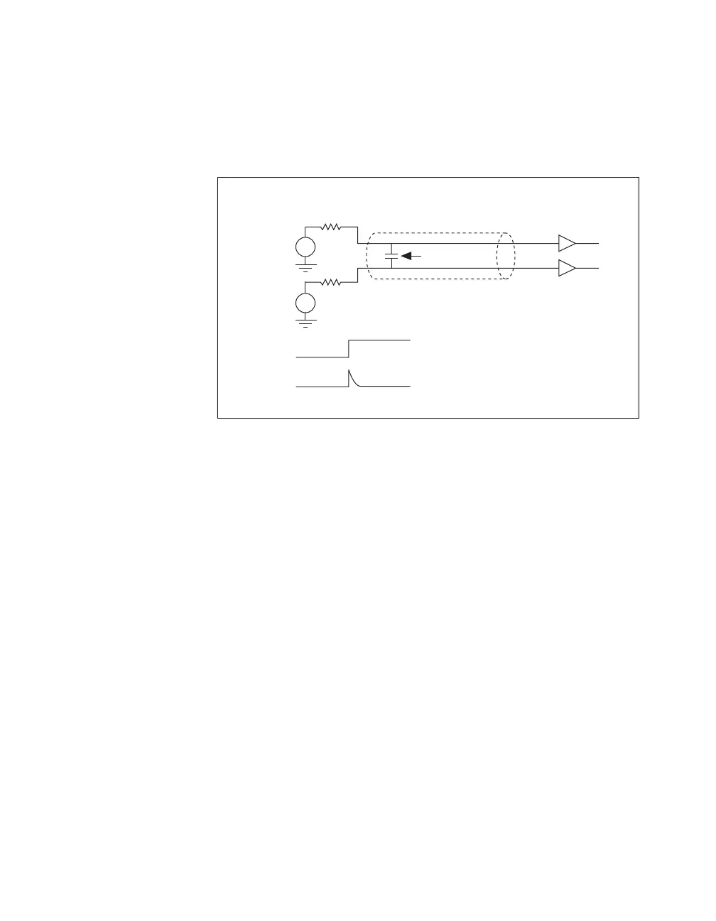
Figure 3-9. Crosstalk Example
In Figure 3-9, PFI 10 and PFI 11 are configured as inputs. V
0
drives PFI 10
and V
1
drives PFI 11. When PFI 10 (the offending line) transitions from one
state to another, it induces a small transition in PFI 11 (the victim line). The
magnitude of the transition (or crosstalk) induced in PFI 11 is proportional
to the following:
• The speed of the transition on the offending line (PFI 10 in the previous
example)
• The length of the cable and the proximity of the victim to the offending
line
• The source impedance of the victim line (V
1
in the previous example)
and the level of the offending line (V
0
)
Crosstalk is most likely to cause measurement errors when the victim line
is at a low voltage. If this crosstalk is 0.5 V or greater, you may get errors
in measurement.
You should not experience crosstalk if the source impedance of the voltage
source driving the victim line is less than 100 Ω. If this source impedance
is larger than 100 Ω and you see crosstalk problems, you should use NI-TIO
filters or a voltage follower with a low output impedance to drive the
victim line.
V
1
V
0
Capacitance
Cable
PFI 11
PFI 10
PFI 11
PFI 10
Z
s1
Z
s0
 Loading...