Chapter 3 Signal Connections
PCI/PXI-6703/6704 User Manual 3-6 www.natinst.com
voltage channel sharing the ground line. You can approach this problem in
the following ways:
– Use a shorter cable to minimize the impedance of the shared
ground line.
– Use separate wiring for VCH and ICH ground return to minimize
common ground impedance.
– Use different pairs of voltage and current channels to keep your
sensitive voltage outputs separate from your higher output current
channels.
Power-up Condition
All current outputs are within ± 1.1 mA maximum of their user-defined
values within 0.5 s of power-up board reset. The current outputs will settle
to their user-defined values to full accuracy within 7 s of power-up board
reset. Take this behavior into account when connecting external devices to
the 6704.
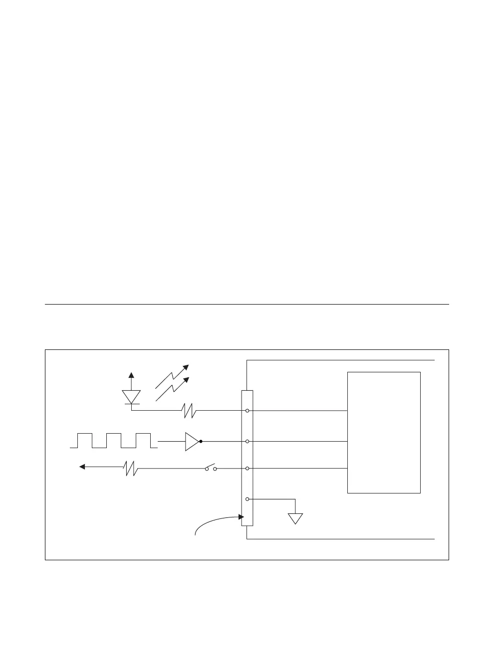
Digital I/O Signal Connections
Figure 3-4 illustrates example signal connections for three typical digital
I/O applications.
Figure 3-4.
Example Digital I/O Connections
Switch
DGND
+5 V
I/O Connector
TTL Signal
LED
R
+5 V
DIO
Line<0..7>
PCI/PXI-6703/6704
Line 0
Line 2
Line 1
 Loading...